   As always, there is a little twisty road on how I came about building the bot. It has been a while since I built a robot and I have been feeling a sudden urge to build my next robot project. Though my instinct is bugging me to build something, the problem is that I just don't have any specific idea or design in mind yet. Well, next thing you know is that the University's IEEE is getting ready for its annual Sumo Robot Tournament for 2014 and the winner gets $500 from USAF along with some goodies. Sounds good to me. | So I give you The Bigfoot. BIGFOOT stands for Ballistically Improvised Ground Field Operated Omni-purpose Tank. Bigfoot is a robotic platform I have been building/researching on recently. The idea is to have a modular track drive platform in which a user can attach different modules for different purposes. For instances, the robot can be equipped with firearms and guidance systems to compliment the "Robotification" of the army. The ground based robotic soldiers such as MAARS are gaining in numbers and popularity. I believe the future wars will be fought by remotely controlled machines during its first phase. Interestingly, did you know that 1 in every 50 troop deployed in Afghanistan is a robot? It can be equipped to serve as a weaponized killer, mobility platform for troops, bomb diffusing, surveillance, and portable rescue vehicle. Another immediate feature would be to replace the weaponry and equip it with a skateboard deck with dynamic balance control to convert the platform as an all terrain personal mobility system for ummm...... civilian joy ride. The potential are vast and I hope to expand its features to make it a Swiss-knife of tracked robots. 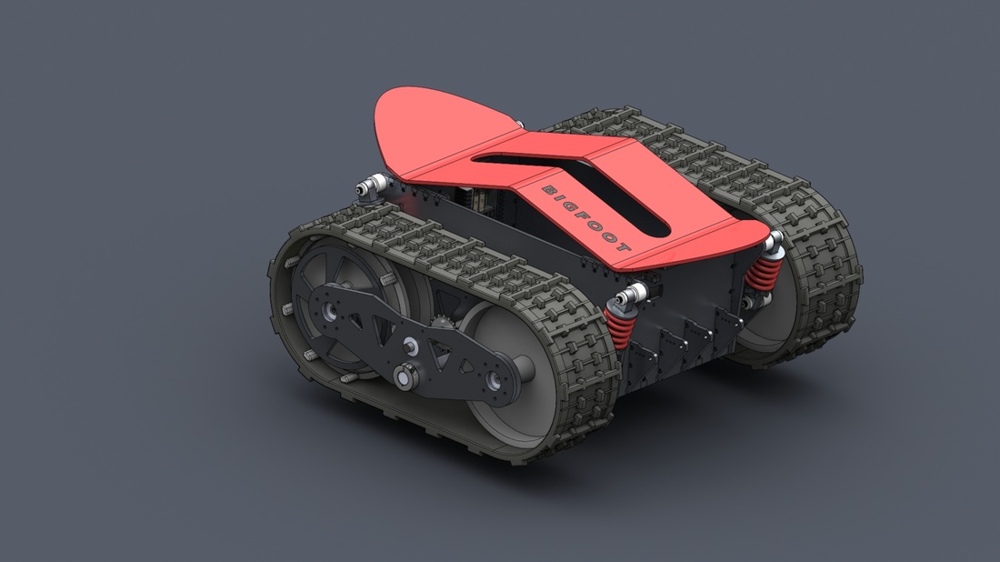 |
Though Bigfoot was inspired by the IEEE sumo robot competition, the size of the tracks I managed to find makes it too big to be eligible to participate. Well, I care less about participating for $500 than thinking how awesome robot this will be if its bigger and powerful as I envision. So, the competition idea is off the drain and I am assigning Bigfoot more noble role of being a research platform for next generation of unmanned ground vehicles with a sophisticated weapon guidance and navigation system. Let Bigfoot's upcoming little brother and medium sized robot TYPHOON do the role of fighting in a sumo ring.
While SR-624 Blackwidow was a huge success in terms of 2013 IEEE Sumo Robot Tournament and manage to knock down 2nd place against an opponent 10 times its weight on a 3 to 1 loss (yep, she pushed off a 60lbf robot off the stage once!!), it also played an unexpected role in inspiring few highschoolers in science and technology through Engineering day expo and other events.
I really don't think the robot is big enough for me to explore or modify further and it seems to be enjoying a retired life without me poking soldering iron through its belly once in a while. Besides, I have been aching to build a bigger robot to be better prepared against my friend's 60 lbf robot ( at least that tournament prompted the IEEE to include weight class for all future tournaments to make it fair for everyone, ha!). Anyways, I badly need something chubbier and powerful. I need a freaking big tracked robot that I can ride on, YEAH!!
Unlike my previous project designs that I wish to claim to be original, this project will mostly be a mutation of designs I came across during my internet research but custom tailored to my tastes and needs.
So, follow me on this thread to learn how NOT to build a robot.
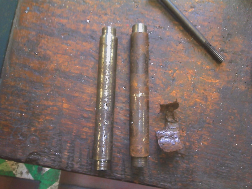
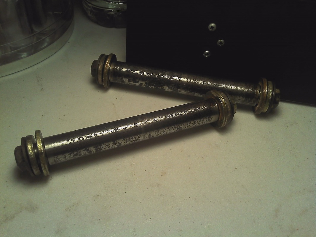
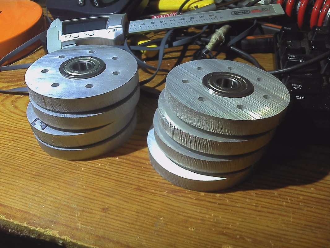
Track drive parts I bought off eBay came with idler wheel and drive wheels. At least the idler wheels came with the shaft was kinda fixed tight so I believe the shafts doesn't rotate with respect to the wheels and the whole wheel assembly is mounted to the frame through bearings or bushings. However, the ebay seller listed the shafts for drive wheels separately and I had to pay an annoying extra for what it seems to be a rusty shaft. Though it looked really rusty in photography, it turns out the bulgy ugliness is actually some sort of nasty 'plasticy' stuff wrapped around - and there was rust too, yeah. A good run through the university lathe revealed that it in fact is a plastic stuff and most probably some sort of bushing I am yet to learn about (which is a good possibility since I don't know much about bushings anyways). Nevertheless, the shaft was corroded and eaten away in some parts as you can see in the before-and-after image. I did not bother cleaning it up all the way in lathe since I would risk the shaft to be too loose for the drive wheels.
Track drive parts I bought off eBay came with idler wheel and drive wheels. At least the idler wheels came with the shaft was kinda fixed tight so I believe the shafts doesn't rotate with respect to the wheels and the whole wheel assembly is mounted to the frame through bearings or bushings. However, the ebay seller listed the shafts for drive wheels separately and I had to pay an annoying extra for what it seems to be a rusty shaft. Though it looked really rusty in photography, it turns out the bulgy ugliness is actually some sort of nasty 'plasticy' stuff wrapped around - and there was rust too, yeah. A good run through the university lathe revealed that it in fact is a plastic stuff and most probably some sort of bushing I am yet to learn about (which is a good possibility since I don't know much about bushings anyways). Nevertheless, the shaft was corroded and eaten away in some parts as you can see in the before-and-after image. I did not bother cleaning it up all the way in lathe since I would risk the shaft to be too loose for the drive wheels.
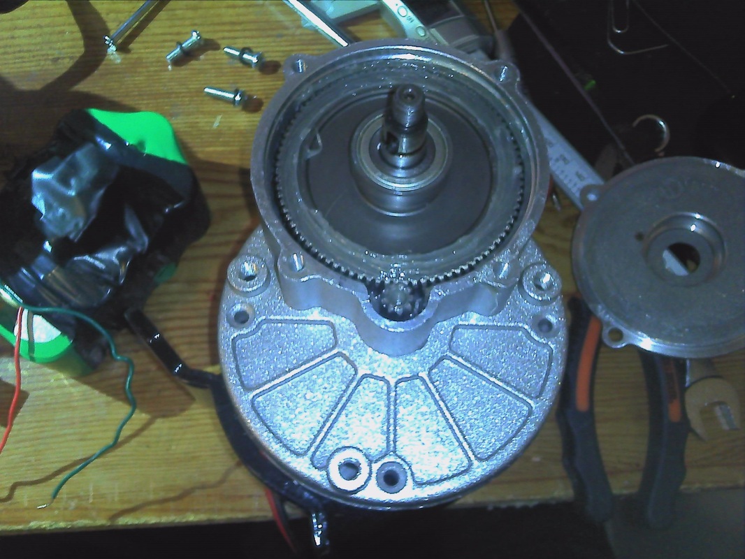
My initial plan was to use two wheel chair motors with the tracks and I went ahead and used two invacare motors that uses worm gear reduction. Though it can provide some significant torque, gearmotor is heavy and bulky not to mention the rpm is low. However, i planned out the design with that motor in mind.
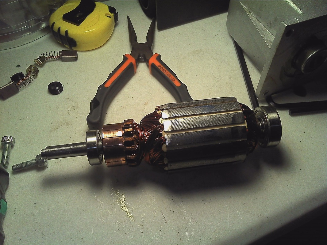
I did took it apart to see the mechanism inside and to remove the braking mechanism which I don't need for the robot. Though you don't have to take the whole thing apart to remove the braking mechanism, I wanted to get an idea of what I am dealing with. It was little trick to put it back as the three long screws that need to be inserted through the back of the motor all the way to the gearbox at the front need to pass through the magnets of the armature. The struggle was that the magnet was attracting and holding on to the piece and makes it difficult to hit the screw thread at the front. anyways, after some struggle, I managed to get it in and closed it down for good.
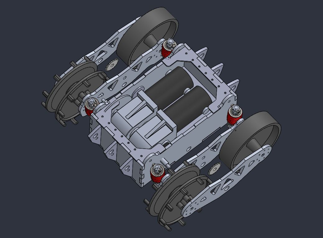
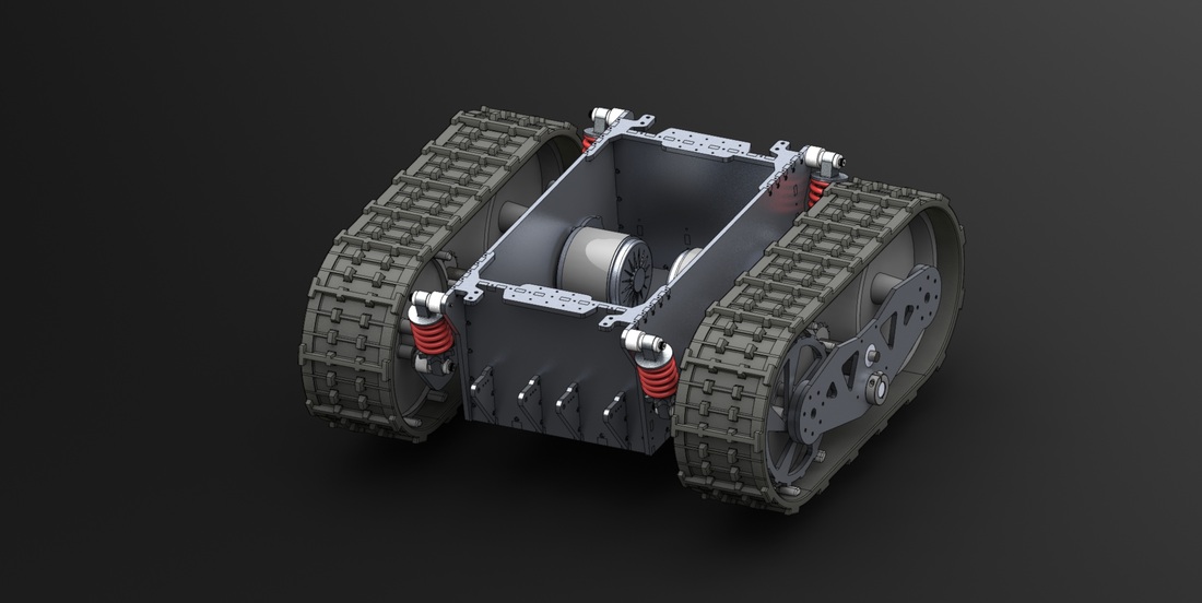
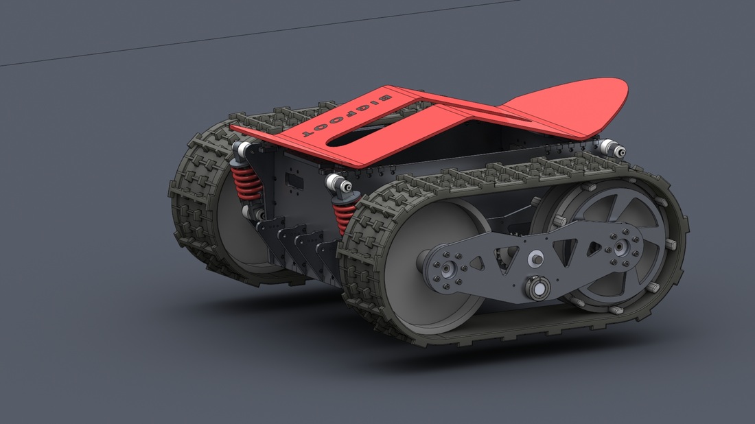
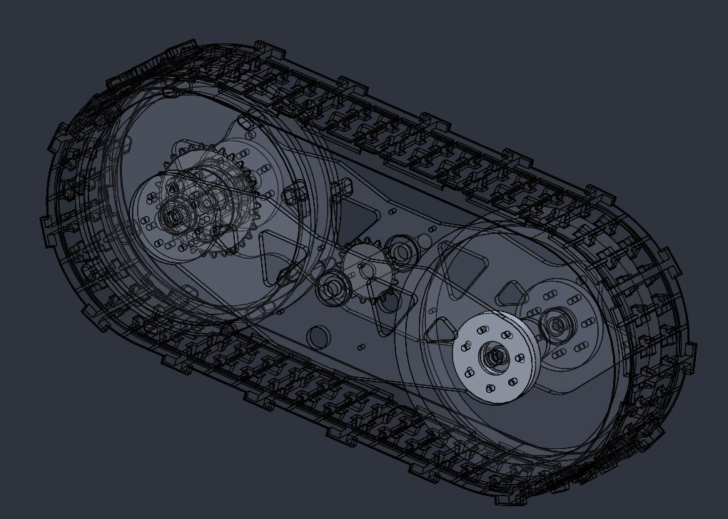
Now that I have a rough idea of what the dimensions should be, I could finally start the CAD process. I recommend people to use CAD as much as possible as they seems to make the design process very efficient with less waster of material later on. I use solidworks as my preferred choice of software. My design was inspired by a community of people that have built tracked robots especially the tracks from snow blowers. The initial design shows Invacare wheel chair motors taking up most of the space.
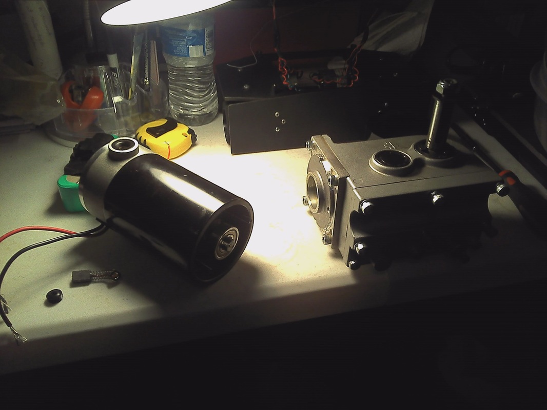
I stumbled upon this 350 W electric bicycle conversion kit motors that comes with a pinion gear reduction with 300 rpm. If one motor has enough torque to push a bicycle rider, then two of them would have enough to power a robot. There goes all the need and opportunity for some engineering calculations out the window. Hey i saved some trees right there (fully knowing that I will be having to comeback eventually and cut down an entire forest for enough engineering paper to workout the calculations what I should have done earlier).But for now, its out the window and my lazy logic prevails.
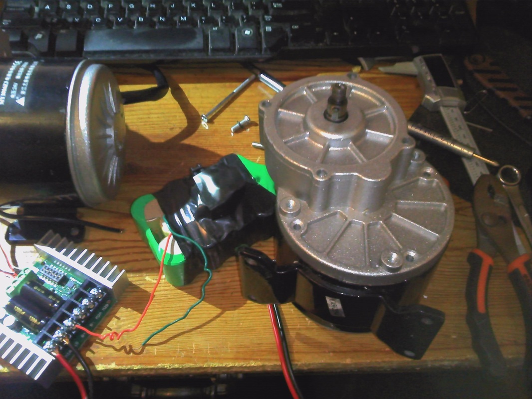 |  |
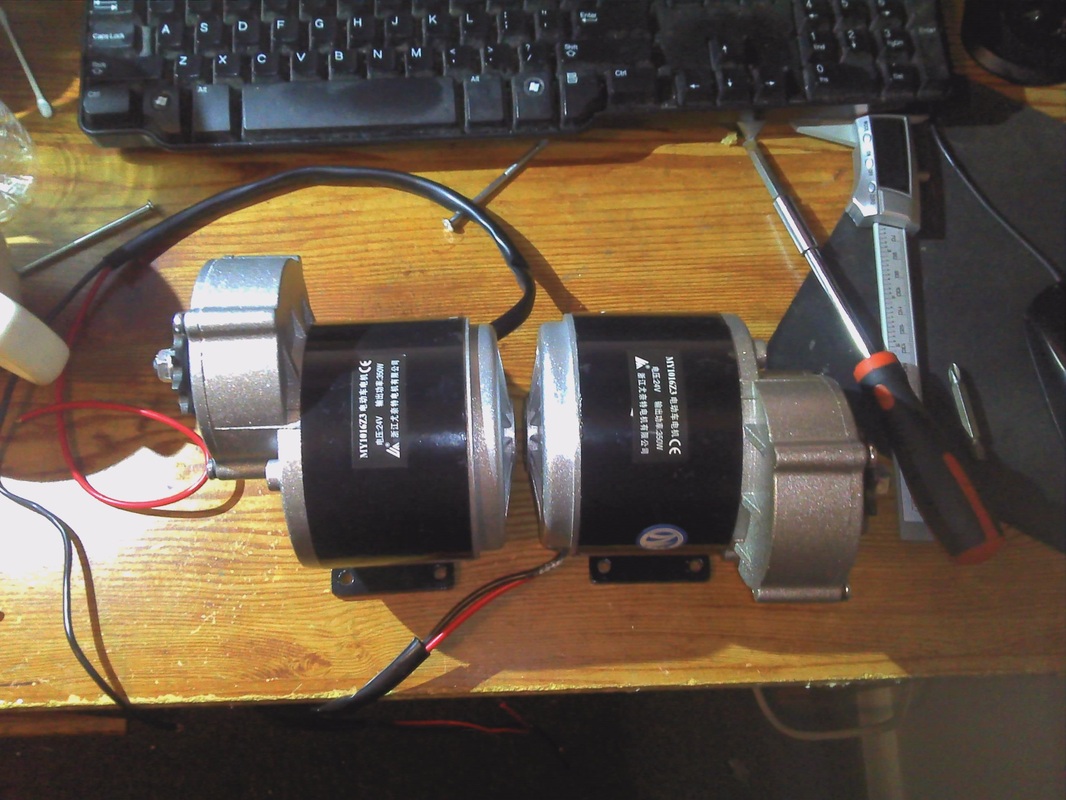
Everything comes with a challenge for some reason. I love the motors but they are not mirror copies unlike the worm gear motors of a wheel chair. It can be made a mirror copy but the base mount metal piece that is spot-welded on to the bottom of the motors prevents it from being mirror copies due to the orientation it was welded on. Either i have to cut it off using a metal cutting saw and use the M6 threaded holes on the side and face mount it to the body or I have to position the motor in such a way that the base mounting piece wouldn't interfere with the body of the robot. Since the later gonna was space inside the robot, I decided to go with the first choice. Time to hit the machine-shop and cut the base mount piece off.
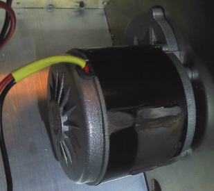
There it is after the piece cut off. The cutting did leave a bruise on the motor body and paint job and I need to cover it using paint before it start to rust or anything corrosive happen.
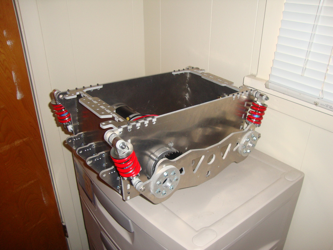
So I finallized the CAD design with motors mounted as mirror copies and with bicycle rear shocks as the suspension. They are, as of now, four shocks in parallel is not gonna budge unless you apply some serious force. The 110mm shocks with 550lb/in springs are in parallel so it gives an effective spring constant of 2200lbs/in. so yeah they are, as of now, equivalent to rigid linkages. Eventually, I will replace the springs with some low spring constant springs and see how that goes as shocks are not a priority in this particular design and I have intentionally left room for future modifications. I got the springs from ebay and negotiated for four springs for around 40 or so instead of the listed 60 price-tag if I remember correctly. The Chinese owner has to make it after I placed the order so it took for a while but it worked out since I wanted red shocks. Obviously, its a cheap Chinese made shocks, It did have some paint chips and scratches here and there by the time I received in the US but it works for me perfect.

So the wheel assembly I designed is such a way that the shafts that are fixed to the idler wheel and drive wheel are placed between two 1/2 bore flanged roller bearings as shown in the image. The bearings are pressed directly into two 3/8" aluminum disks. the screw holes allow the disks to be able to mount it to the 1/4 aluminum assembly frames. The disks needed to be waterjet cut and threaded.
So, I just waterjetted the bearing disks and realized my stupidity that I didnt bother to consider the tolerance for the bearing hole. The hole diameter was exactly what I measured off the bearing with caliper so I ended up having difficulty pushing the bearing in. To make things worse, waterjets are notorious for creating taper (depends on how bad your machine is) to the work-pieces. Apparently, my 3/8 aluminum parts had slight taper also which made things worse. Oh well, lesson learnt (hopefully) and its time for some Dremel action to make the holes slightly bigger so I can fit the bearings in, finally. Oh btw, I have 8 of those disks to clean up so its gonna be fun...NOT.
So, I just waterjetted the bearing disks and realized my stupidity that I didnt bother to consider the tolerance for the bearing hole. The hole diameter was exactly what I measured off the bearing with caliper so I ended up having difficulty pushing the bearing in. To make things worse, waterjets are notorious for creating taper (depends on how bad your machine is) to the work-pieces. Apparently, my 3/8 aluminum parts had slight taper also which made things worse. Oh well, lesson learnt (hopefully) and its time for some Dremel action to make the holes slightly bigger so I can fit the bearings in, finally. Oh btw, I have 8 of those disks to clean up so its gonna be fun...NOT.

Well, I survived the grinding. The struggle is real and hopefully it will keep me alert next time to consider factor in cutting tolerance and errors. Never seen such a beautiful stack of aluminum disks (ignore that massive waterjet taper on the sides btw)
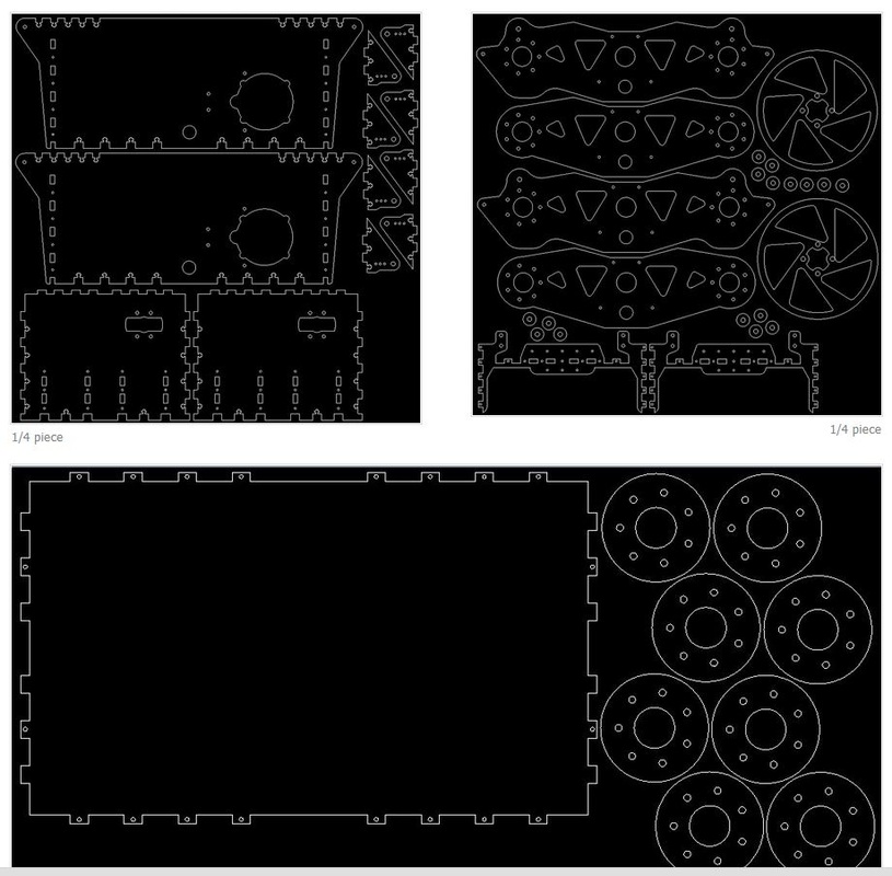
I had to wait for two more weeks till I get to order one more sheet of aluminum and some parts from Mcmaster as this project is solely funded by my broke student wallet. so, finally got the rest of the parts in and decided to hit the protolab again. I usually organize and layout all the in a way that i waste less material on the sheet. Here is the dxf image i used to cut the parts out of the 24x24 plate. The third piece which consists of the bottom plate of the body and the disk bearing housing pictured above were cut off of 3/8 aluminum. 3/8 worked great for the disks as they needed some thickness but using the plate for bottom piece was an overkill.

Proto-lab is awesome! lab has few of my favorite machines when it comes to projects like these. Proto-lab was introduced and managed by the grant written by Dr.Crittenden, an engineering professor at Louisiana Tech University. More information can be found here.
Kern Micro 48 Laser Cutter 100W (work area 24inx48in)
Omax 2626 Waterjet (work area 24inx24in)
What laser cutter cannot cut (such as thick metals), I use waterjet. When it comes to 3D printing, Thingery is the choice. I was too shy to walk into the protolab till i was in my sophomore years. But once you get the feel of it, you would just get addicted to the spike in the quality of your projects.
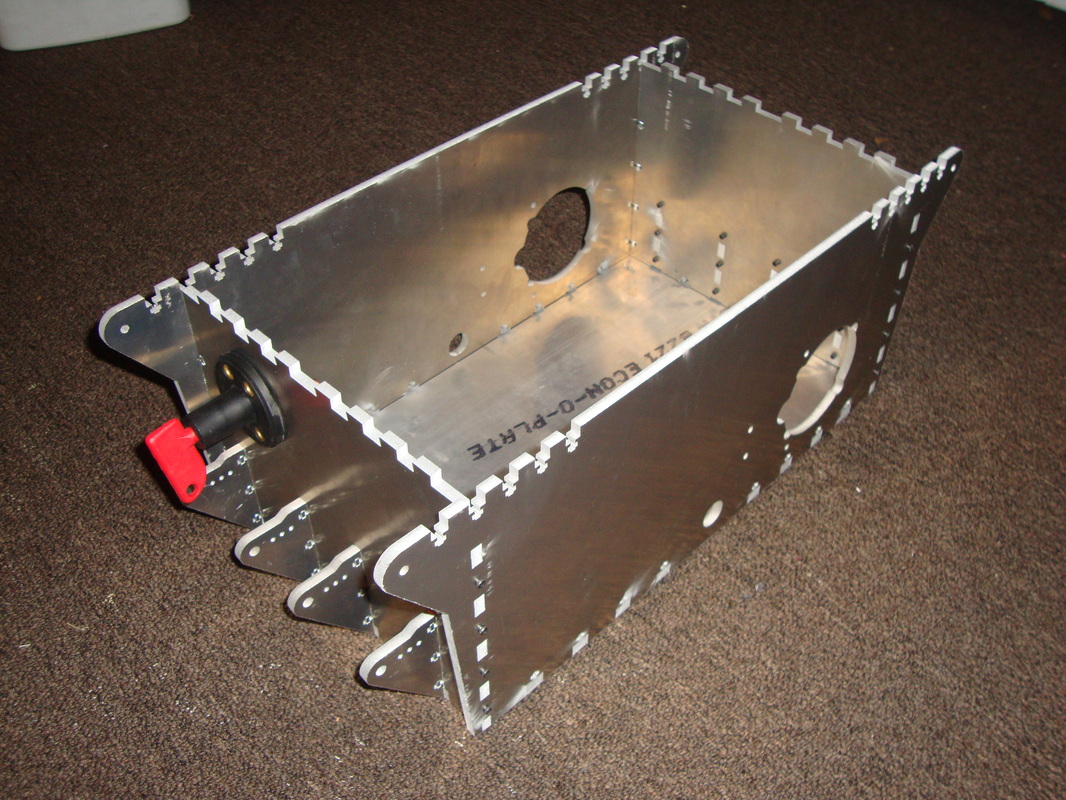
The body assembly went smooth as I had all the aluminum sheets cut and ready to go. The few issues were the threading of some 100 plus holes. By the end of threading, I looked like the Charger from Left4Dead with one arm all pumped up and the other is as skinny as it usually is. okay maybe not that extreme. Either way, body assembly was relatively smooth.
Kern Micro 48 Laser Cutter 100W (work area 24inx48in)
Omax 2626 Waterjet (work area 24inx24in)
What laser cutter cannot cut (such as thick metals), I use waterjet. When it comes to 3D printing, Thingery is the choice. I was too shy to walk into the protolab till i was in my sophomore years. But once you get the feel of it, you would just get addicted to the spike in the quality of your projects.
The body assembly went smooth as I had all the aluminum sheets cut and ready to go. The few issues were the threading of some 100 plus holes. By the end of threading, I looked like the Charger from Left4Dead with one arm all pumped up and the other is as skinny as it usually is. okay maybe not that extreme. Either way, body assembly was relatively smooth.
 |  |
Most of the build project went without much hassle then I had to install the chain drive. If there is one thing you should know about chain that its messy, at least for me. Bigfoot officially is the first robot (any machine in that regard) that I am incorporating chains. The issue was the slack. Since I decided to assume that adding chains to the design will be an easy task, I didnt consider any of that in my CAD work. Damn you, Murphy's Law, that is where all the trouble started.
The #35 chains I used were too lose and the only way I could get that slack off was by removing the two adjacent links. Chains are built such that Two wider plate links are connected between a small plate link. The problem is that if you only wanted to remove one smaller plate link, then you ends up with two wider plate links as neighbors which makes it impossible to connect the two wider plate links. Or the other way, If you remove one wider plate link, then you would end up with two smaller plate links as neighbors.
I needed to get rid of two links but that would make the chain tiny bit short and I wont be able to connect the links and since the links are steel, they wont stretch either. Even if I manage to make it stretch to connect, the chain will be too tight and will be impossible to get into the sprockets.
So, the solution was to get rid of one link then put a chain tensioner on to get rid of the slack. Now this is where the Offset chain link comes into play. While doing resesarch, I came to know that there is a special kind of chain links called Offset links that are specially designed to solve two link removal issue. As shown in the figure, one side of the offset link is wider and the other side is narrower. This charecteristics allow the link to be used as a single link replacement instead of having to replace two links. Now, the offset link came with a cotterpin, but my #35 chain link removal tool worked okay with the push pins.Figure shows offset link along with the two links I had to remove.

Now that the chain length was cut short by one link, there is still significant amount of slack that I cannot get rid by removing another link. So, the way out was to put a chain tensioners. There were plenty of chain tensioners available in the market but those are either expensive for my broke student budget or cant be used in situations where the chain runs in both directions etc. So, I decided to improvise my own chain tensioner the Ghetto style.
This chain tensioner is not a final design I will be using however, it works good as for now. I certainly have to figure something that is spring-loaded to make sure there is absolutely no backlash at all and runs smoothly.
This chain tensioner is not a final design I will be using however, it works good as for now. I certainly have to figure something that is spring-loaded to make sure there is absolutely no backlash at all and runs smoothly.

As you can see, I used skateboard wheels bolted to the frame as my chain tensioner. It works but doesn't have the flexibility since its mounted rigid.
A spring loaded tensioner will be more desirable for future modifications. The picture shown above has the wheels before I cut a chain groove in the middle to make sure the chains are not slipping out. I have a total of four tensioners in all four chains. Two wheels are mounted inside the tracks and two are wheels connect the motor to the tracks.
A spring loaded tensioner will be more desirable for future modifications. The picture shown above has the wheels before I cut a chain groove in the middle to make sure the chains are not slipping out. I have a total of four tensioners in all four chains. Two wheels are mounted inside the tracks and two are wheels connect the motor to the tracks.
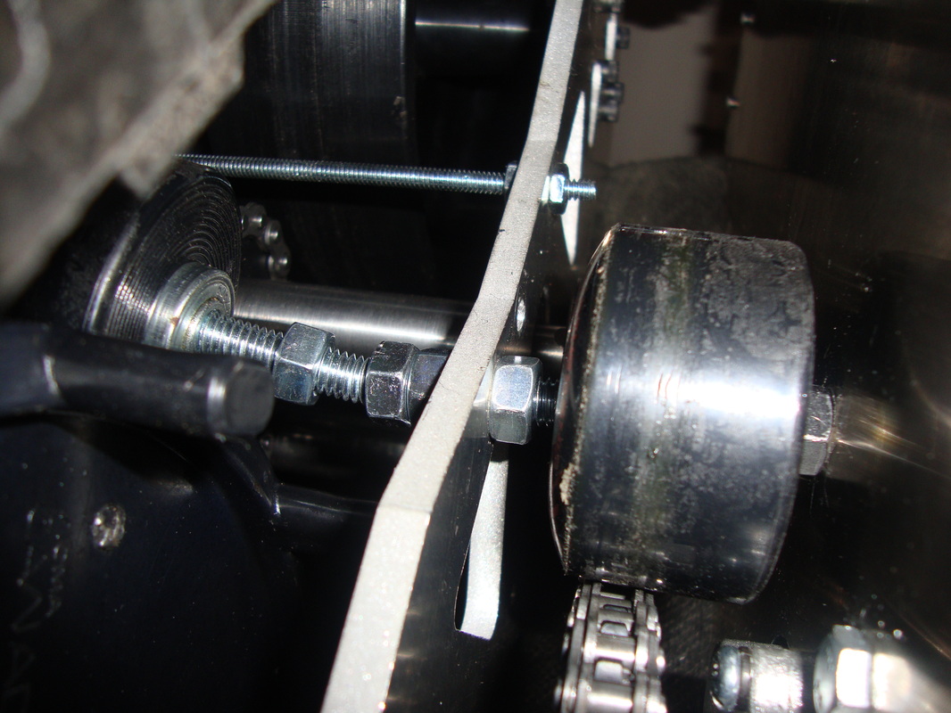
Now, I initially mounted the wheels inside the tracks in a cantilever manner but I totally under estimated the tension through the chain and it bent the 5/16 in bolt like a piece of melted plastic. Figure shows the left wheel inside the track assembly and the right wheel that give tension mounted to the body outside the chain assembly.
So, I ended up getting a longer 5/16 screw and mount it between the two aluminum plates. Now they are at Double shear and the load is at the mid center which is desirable than the single shear cantilever support.
So, I ended up getting a longer 5/16 screw and mount it between the two aluminum plates. Now they are at Double shear and the load is at the mid center which is desirable than the single shear cantilever support.
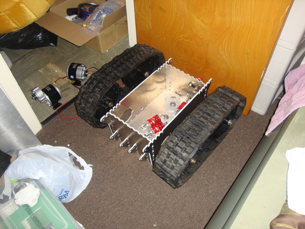
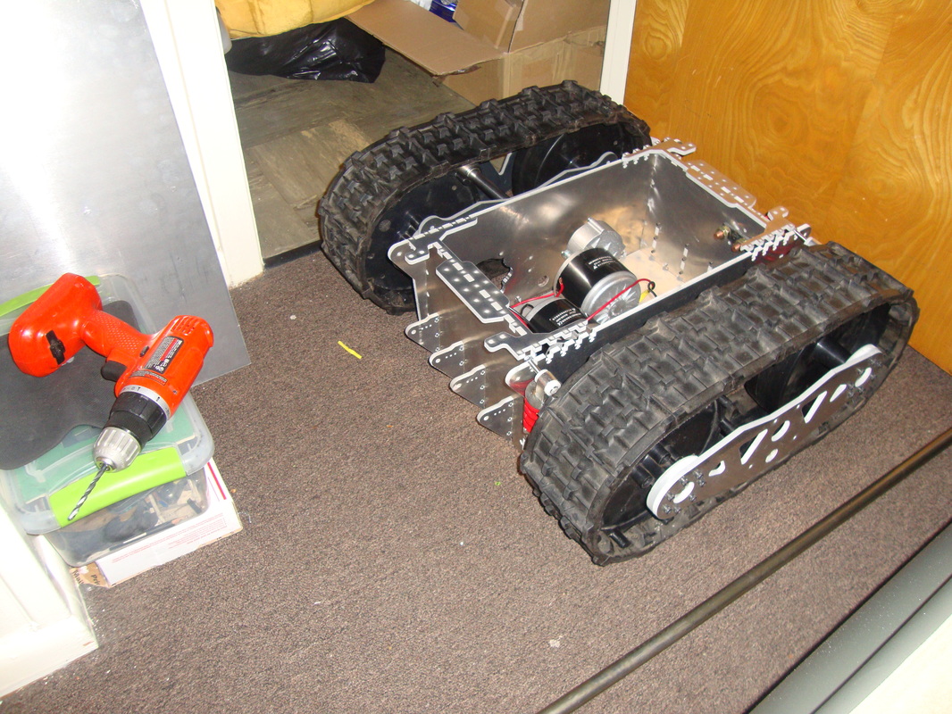
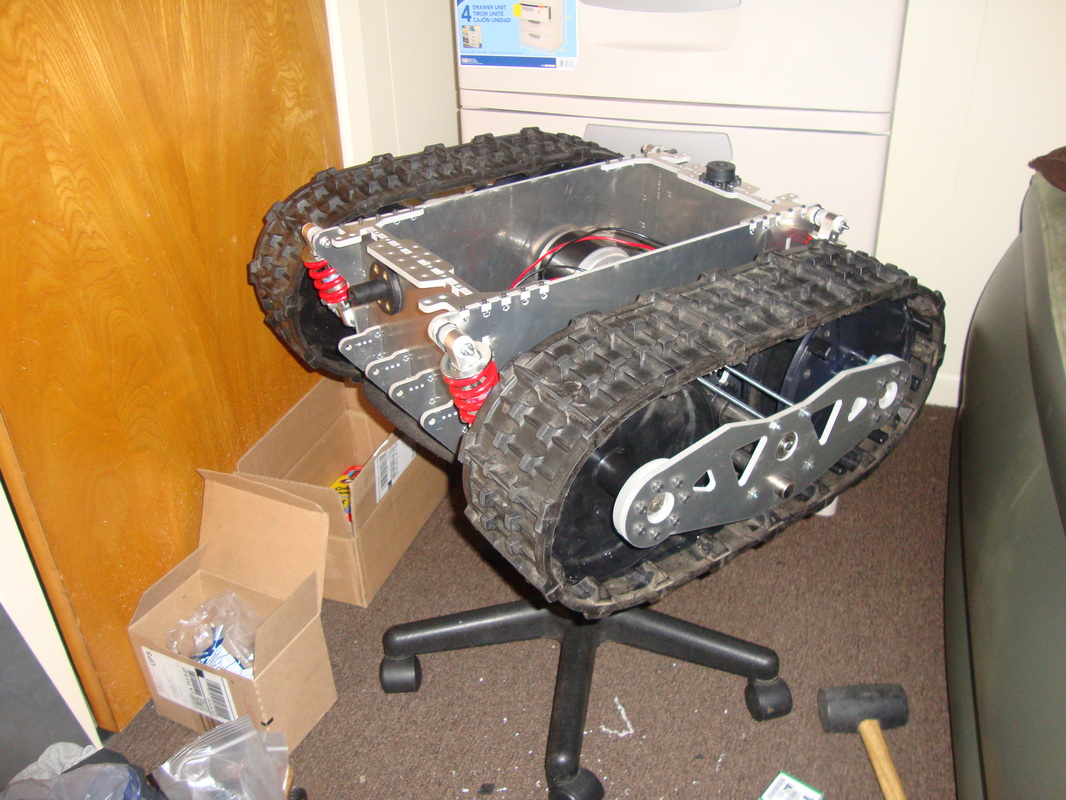
So there he is coming together...
Ahhh....let the wiring begin!
The idea is to use two 18Ah sealed lead acid batteries as my preferred choice of LiFePo batteries seems to be super expensive. maybe eventually I will upgrade it to LiFePo but for now SLA batteries works perfect if I ignore the extra weight. I am using a Turnigy Accucell-6 charger that I bought for another project for charging the SLA battery. It can charge Lithium and leadacids which is pretty neat and handy. So, I have two choice. Use two 18Ah in parallel give me 12V and 36Ah and enjoy the longer drive time or use 18Ah in seriies to give 24V and 18Ah which would put BIGFOOT three times faster than iRobot's Packbot or two times faster than MAARS robot. He has a theoretical speed of 15mph at 24VDC which is what the motors are rated for. Anyways, I might formulate some kind of mechanism to switch between series and parallel with the flick of a button if possible.
The idea is to use two 18Ah sealed lead acid batteries as my preferred choice of LiFePo batteries seems to be super expensive. maybe eventually I will upgrade it to LiFePo but for now SLA batteries works perfect if I ignore the extra weight. I am using a Turnigy Accucell-6 charger that I bought for another project for charging the SLA battery. It can charge Lithium and leadacids which is pretty neat and handy. So, I have two choice. Use two 18Ah in parallel give me 12V and 36Ah and enjoy the longer drive time or use 18Ah in seriies to give 24V and 18Ah which would put BIGFOOT three times faster than iRobot's Packbot or two times faster than MAARS robot. He has a theoretical speed of 15mph at 24VDC which is what the motors are rated for. Anyways, I might formulate some kind of mechanism to switch between series and parallel with the flick of a button if possible.
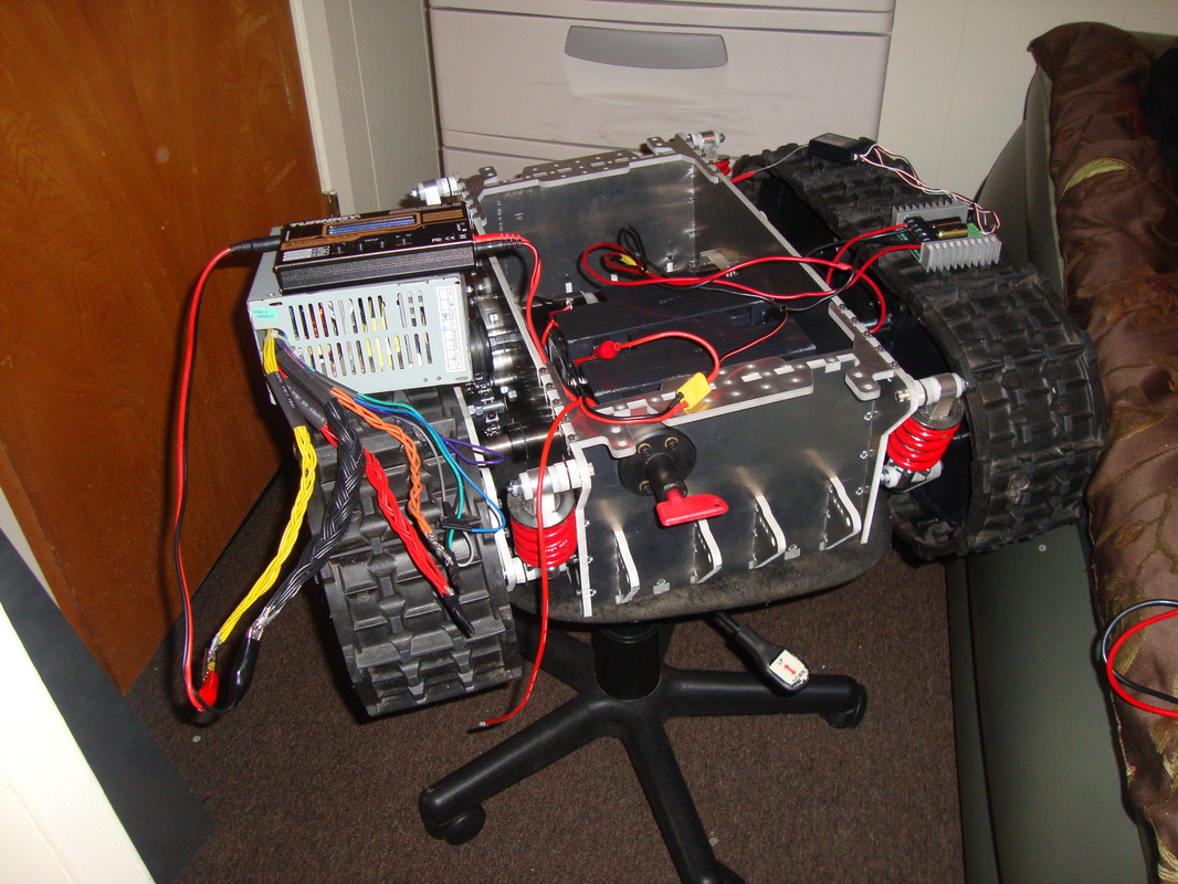
Though Accucell-6 is an awesome charger, they wont provide you with a power supply and you have to use 12 and high amps if you want to charge in high amps. I ended up modifying my own powersupply using an ancient Dell computer's ATX unit. The yellows are 12V and they are capable of putting out some serious amps. The figure shows the ATX unit on the left with all kind of wires coming out. I still need to get it into a neat plastic box before I burn down the building with some freak short circuit.
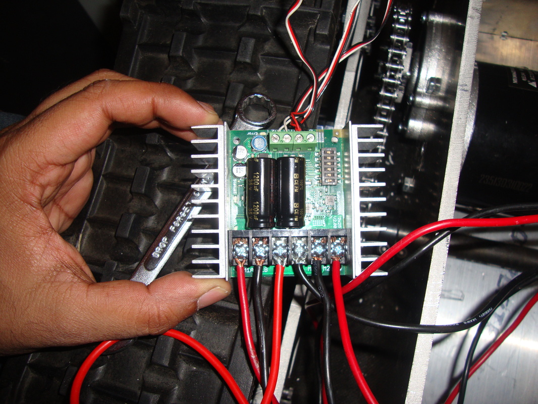
The motor controller is Dimension Engineering's Sabertooth Dual 2x25A boards. They are awesome. The very first time I used their board on a robotic project was Blackwidow and I loved it. The Blackwidow board was 2x12A which means it can handle two motors rated at 12A each. The power hungry motors of the Bigfoot would fry the 2x12As so I ended up getting their elder brother 2x25A, and oh, they come with built in passive heat sinks. Man I sounds like a sales rep for Dimension Engineering and should get paid. Anyways, they are awesome so far.
I will be controlling the robot using a Turnigy 9x radio and reciever combo for testing and fun purposes. Eventually, the goal is to equip with navigation systems based on kinect and if a tree with leaves made of dollar bills get some LiDARS. Kinect I can see a reality since I put a bid on ebay for one and we shall see. The Sabertooth can be controlled using microcontroller or radio input so the possibilities are there. Now, as a side note, I definitely wont be running the machine at 24VDC with autonomous navigation as I am no Ussain Bolt to capture the runaway beast at 15mph, which is very likely to happen till I really nail the navigation algorithm which is very unlikely to happen.
I will be controlling the robot using a Turnigy 9x radio and reciever combo for testing and fun purposes. Eventually, the goal is to equip with navigation systems based on kinect and if a tree with leaves made of dollar bills get some LiDARS. Kinect I can see a reality since I put a bid on ebay for one and we shall see. The Sabertooth can be controlled using microcontroller or radio input so the possibilities are there. Now, as a side note, I definitely wont be running the machine at 24VDC with autonomous navigation as I am no Ussain Bolt to capture the runaway beast at 15mph, which is very likely to happen till I really nail the navigation algorithm which is very unlikely to happen.
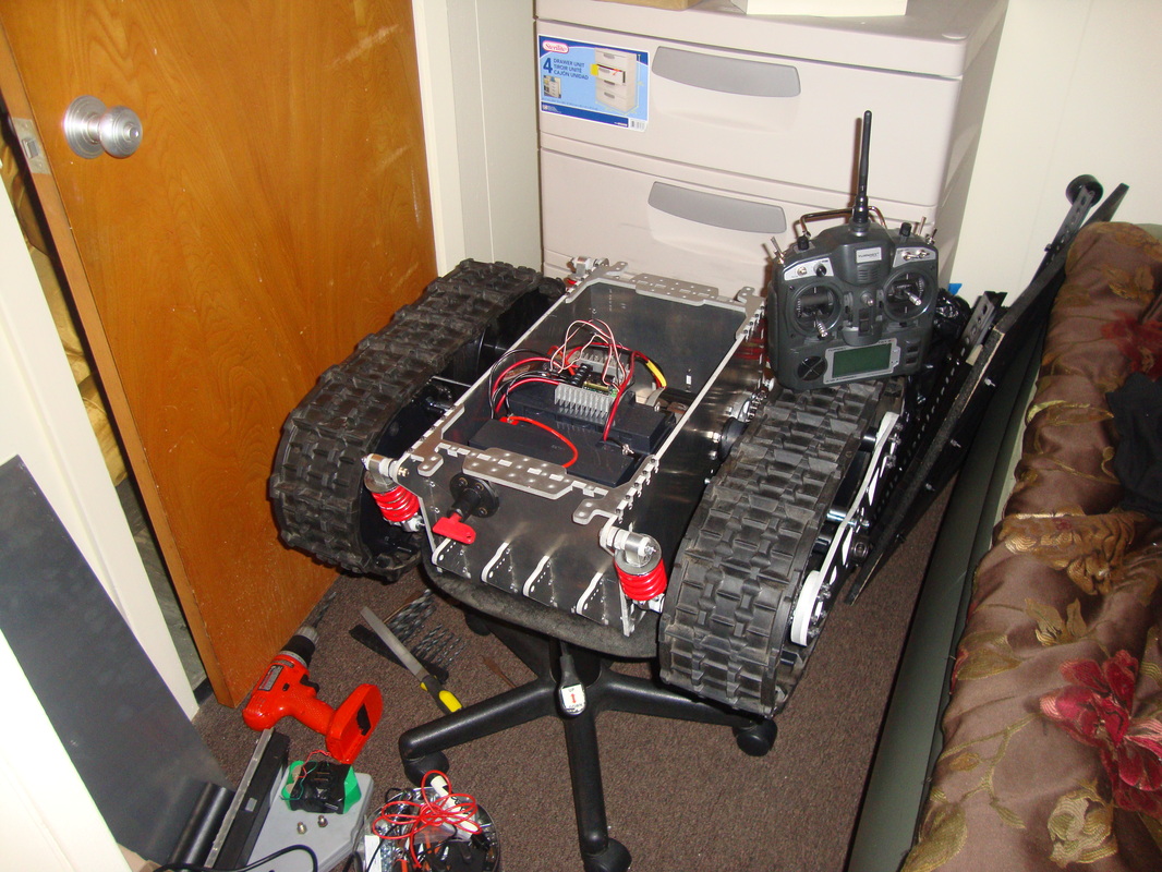
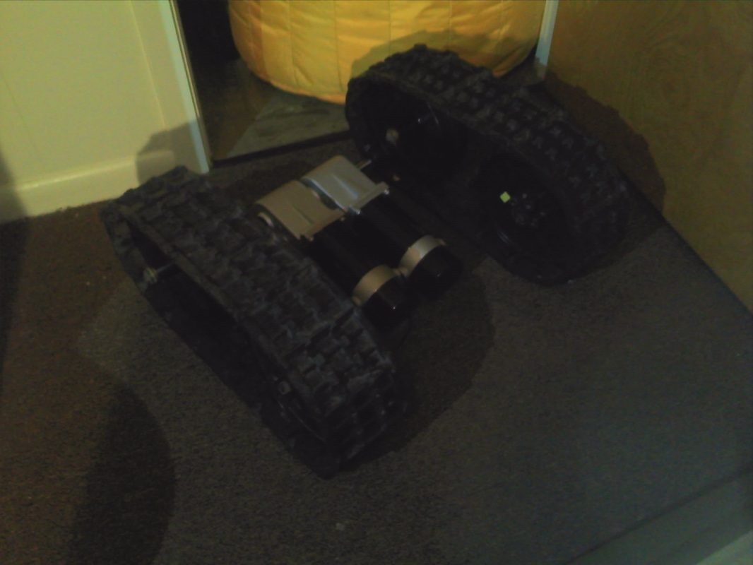
So he is finally ready for some testing outside. I hooked up just one battery and left the other one as a spare since I dont know howlong it gonna last in real life scenerio. It was a good day since Louisiana Tech's Thingery Facility was having some news channel coming over and wanted to see some student projects. I got invited by the Thingery since I am a regular there along with few other students. So I took him there for Bigfoot's very first adventure outside.
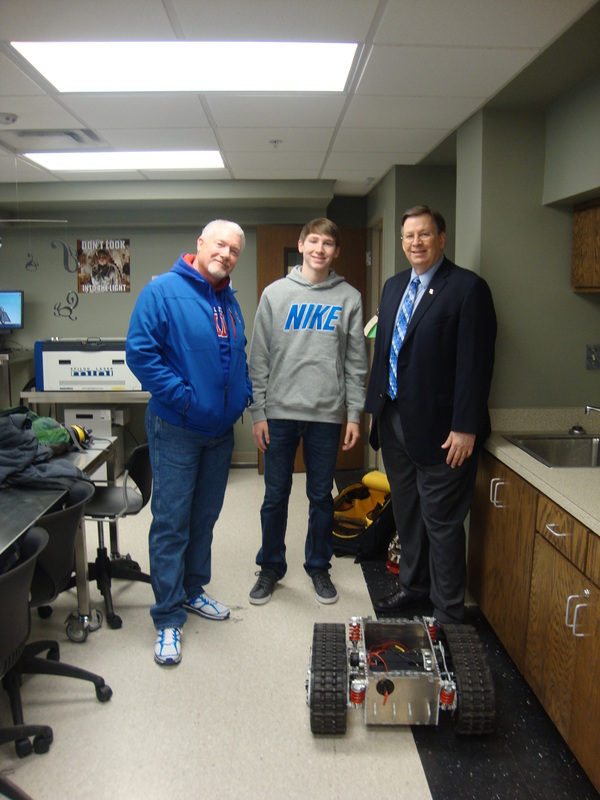
It all went nice and all till the President of Louisiana Tech University walked in for some random reason. So I asked for a picture with him for purely bragging purposes. Have no clue who the other two people on the left are.
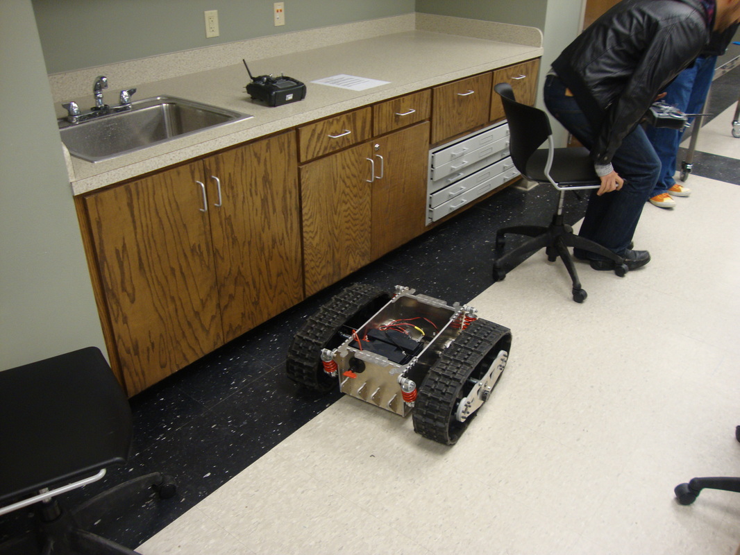
Though Bigfoot didnt go into the main campus and pretty much spent the day at the Thingery lab, it was a pretty successful day. People had fun riding it and driving it. Took him out on the grass next to the lab and I randomly decided to make him climb the stairs and it flipped over. So, for your pelasure, the fail video is also uploaded there. The batteries are not secured so its just floating inside the chassy and the wirings are crude and not finalized since its the first test. So, I enjoyed the win and fail for the first outdoor test.
here is the LINK to the news piece
here is the LINK to the news piece
| | |
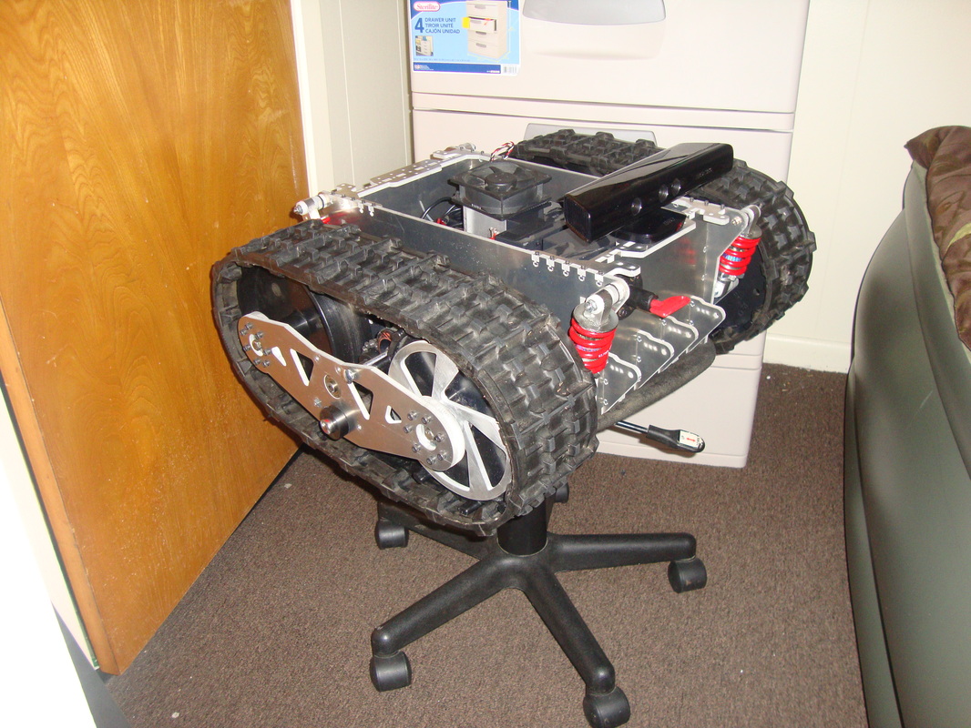
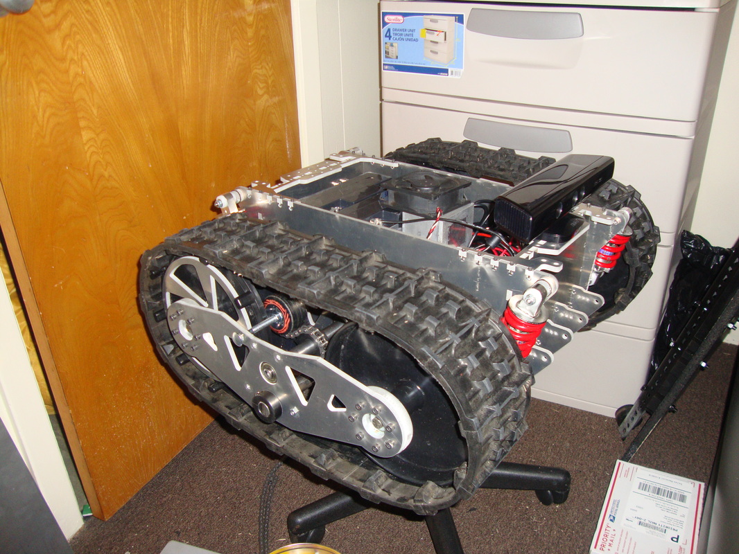
So apparently I won the bid (which never happened before in my ebay life) and got my kinect shipped after some delay since the sender failed to respond for a week and I ended up opening a case. Well, he finally responded that he had some family emergency and sounded like a nice guy and I withdrew the case and it all worked out. So got my kinect today and put it on top of Bigfoot. He finally got a face.
Its very rare to have snow in Louisiana so I was pretty disappointed that I may not get to test out its snow blower tracks but hey it worked out. It snowed and I took him out for a spin. I didn't have the battery and electronics secured and waterproofed it as the snow was totally random. So I covered the battery and sabertooth with plastic bag and off he goes...
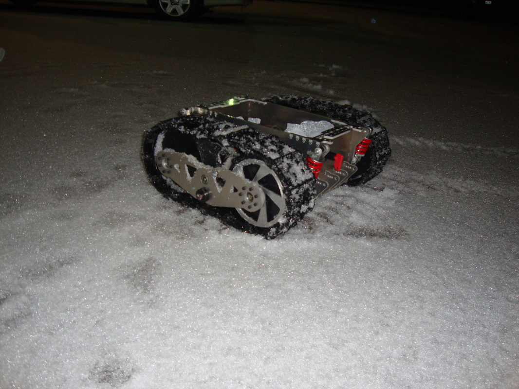

So i did some checkup on the machine after it was left to de-ice in my kitchen tiles since it was covered in all snow. Wanted to see if snow is getting piled up in any undesirable manner. I have heard stories online with snowblower tracks that have snow piled up into the space between the wheels and eventually cracking of slipping the wheels out. Sounds reasonable to an extent but I cannot confirm it since its internet and anything is possible. In the case of Bigfoot, it seems like the ghetto tensioner mounting screws prevents snow from getting deep into the space between the drive wheels and seems scrapping it off. However, snow did piled up between the wheels in a non-problematic manner. Did a thorough inspection and saw one screw mission (as shown in the image to the wheel shaft on the left bottom corner). Turns out, I didn't put the screw on in the first place before I took it out on snow so no worries. I installed it back on with some Locktite. Bigfoot survived the winter test.
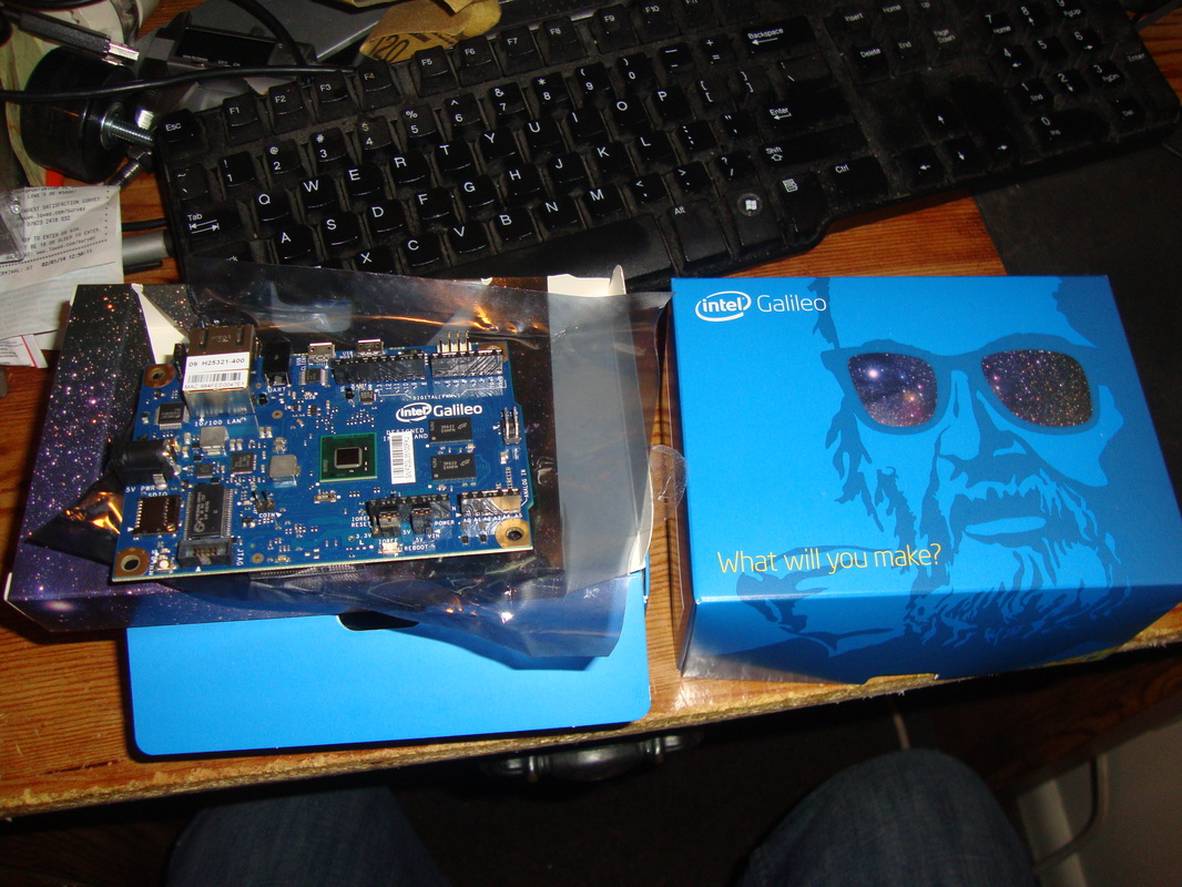
I recently applied for Intel Galileo grant proposal through the Thingery lab of the Louisiana Tech University and I ended up winning one unit. Sweet. Now, BIGFOOT officially will be powered by Intel. Intel is in a collaboration with Arduino so it pretty much is Arduino with intel badge. I am still in the process of learning it as it seems to have built in Ethernet port and SD card slots and many more goodies. The learning curve shouldn't be that deep since you can use the arduino sketch to program it and should be fine. Excited and I should have some updates on programming when I figure everything out.
DISCUSSION SECTION