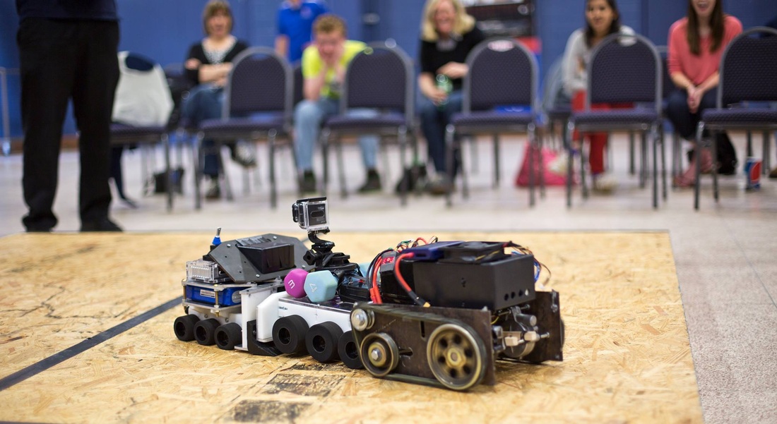
It all came down to this moment. A snapshot from the event when Typhoon (left) pushes two of its opponents with a combined weight twice that of its own body. Pure pushing power.
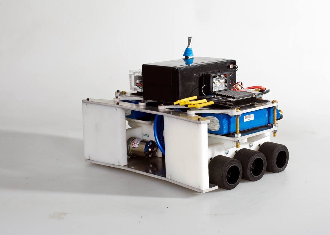
Finished robot without the front scoops
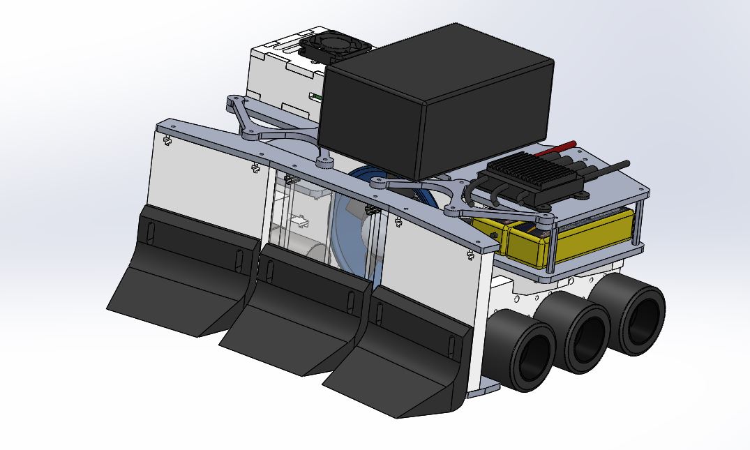
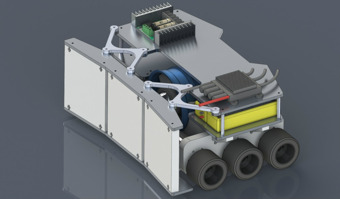
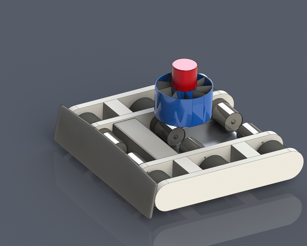
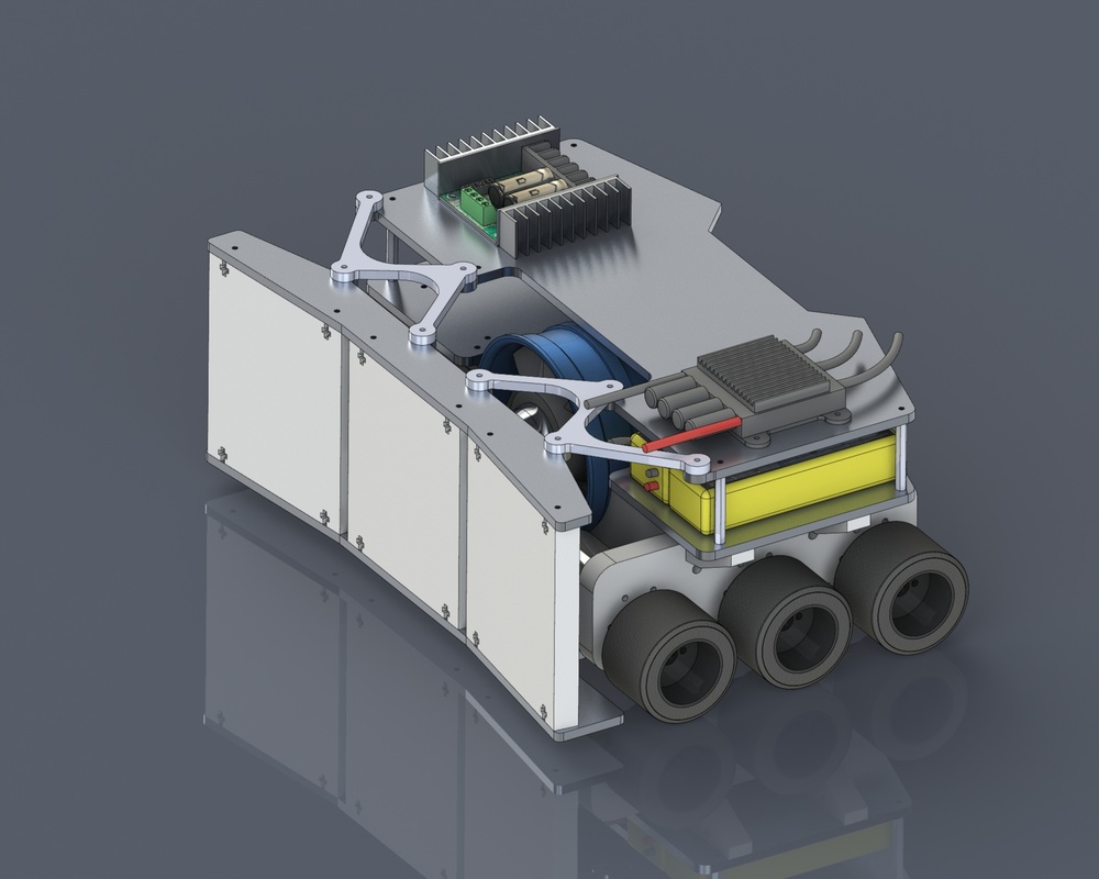
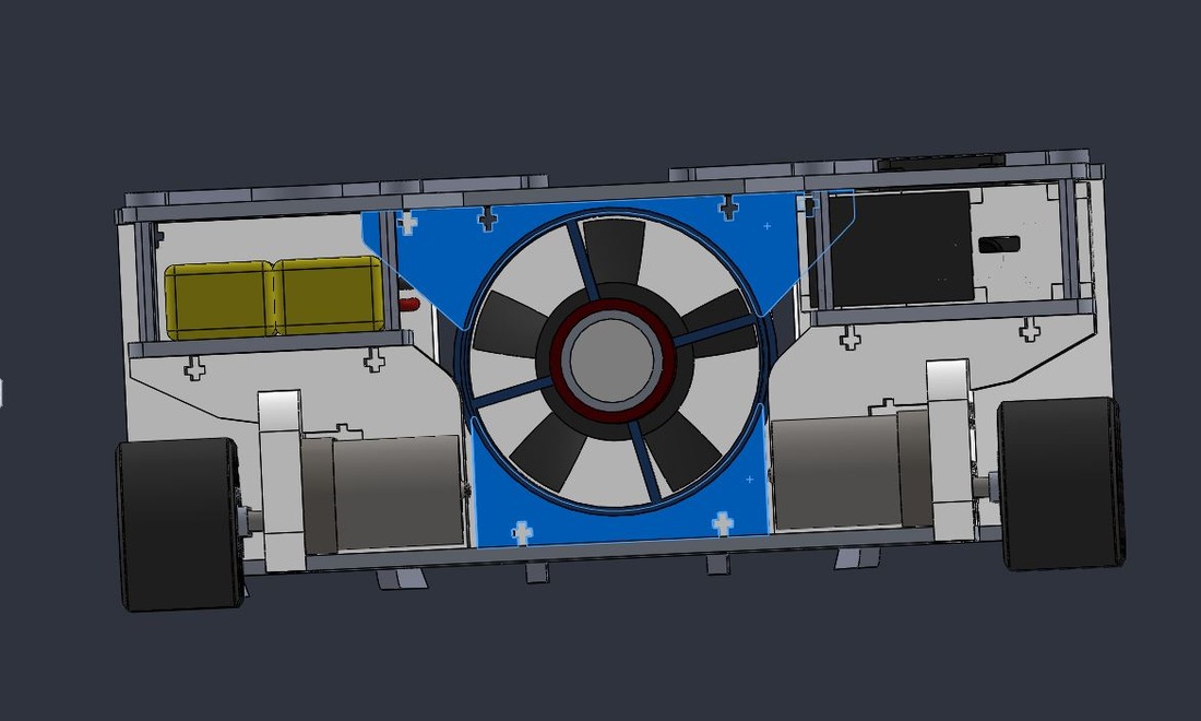
Typhoon with its completed CAD model. The robot was fully designed and tested in Solidworks before even the first part was made. The CAD and FEA help reduce the cost while increasing workflow efficiency.
Its that time of the year again to participate in the annual Louisiana Tech University IEEE sumobot competition. Rule book says there will be at least two weight categories this time - Light weight (upto 5lbs) and medium weight (5lbs - 15lbs). Light weight category is right in line for Blackwidow, of course with slight modification. Now, big prize money is on the medium size and I have no robot of that size laying around. The design and brainstorming process is on...
The core idea of a sumobot challenge is to make the robot generate highest pushing force. Pushing force is the frictional force in this case.
Ffriction = uk x Fnormal
F normal is the vertical force component of the robot applied to the surface its on. In most cases, its the weight. So, as you may have already figured, the pushing force of the robot is directly related to its weight. Well, everybody knows that, but hey, if you know the physics behind it, then u can start messing with the physics to give you a leverage. For instance, there are two ways you can improve the frictional force here.
- Increase the coefficient of friction
- Increase the Fnormal
Increasing the uk in real world terms mean to get a wheel/track that have better grip. No matter how much torque or weight your sumobot can produce, if you cannot transmit them into the surface, its worthless. That is where coefficient of friction comes into play. I would love to add a track drive system like bigfoot (mostly for aesthetic purpose) but the track drives that are available in the market seems too expensive and well over my budget; more over, they wont necessarily give you a high uk. Interestingly, on a side note, I bought Bigfoot's track drives originally for IEEE sumobot competition but unfortunately, its too big for the entry rules. Nevertheless, I had to make a robot around it somehow and so I did. Well, in a weird way, Bigfoot was born and he is doing what he do best - being awesome! Now, the wheels i have been using for Blackwidow are quiet reasonably priced and seems to have a high coefficient of friction. So, I plan to incorporate the trusty old Blackwidow wheels for her new sibling and that should take care of the uk aspect.
Another part of the friction equation is the Fnormal. Well lets be real here, can you increase the Fnormal somehow? Damn straight you can! As I mentioned earlier, its pretty much the reaction force surface generate against the vertical component of the force, so usually the weight. Now, if you can add some extra vertical forces along with the weight, then the normal force can be increased. For instance, a common choice is to use magnets on a metallic sumobot ring. The attractive force of the robot to the ring increases the normal force and produce quite high pushing forces. Heck, you can drive such robots on a vertical surfaces as shown in the video below.
Now, before you think I am gonna add some big ass magnet to my robot, I have to admit the reality that the IEEE sumo ring is not made of iron or steel but by OSB! So the magnet idea is out of the drawing board. Well, what else can give you an additional down force? a vacuum pump or a freakin turbo jet engine! what? I am not kidding there are scaled down jet engines out there for hobby aircrafts and such. Since rule says 'no flames' in all caps, i am investigating vacuum pumps or something of that sort.
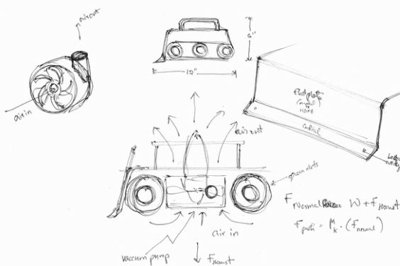
Idea is to have the vacuum pump face downwards so I am, in effect, making the robot stick to the surface as a suction cup! But i dont want to narrow down to that idea this early yet. Google is showing me more and more gadgets that can use instead of vacuum pump.
I found this interesting video of a guy driving his robot through the ceiling upside down using a hobby EDF (Electric Ducted Fan). I checked the prices and BOOOOOM its somewhat affordable. Plus it sounds soo coool!! Moreover, what if I can make the EDF tilt to make it switch from vertical to horizontal, that would be interesting.
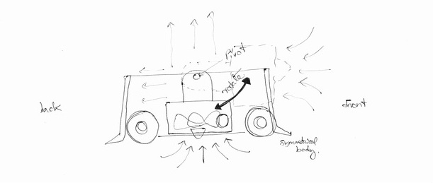
I have made a couple of iterations of the concept to see which one flows better as far as the robustness and effectiveness is concerned.
Iteration 1
Iteration 2
Iteration 3
I liked the iteration 3 better since the EDF is oriented horizontally. I theory, this is an alternative way of getting the maximum direct push instead of going into the friction. Idea is to use the thruster only when its needed. For instance, if I pump the thruster all the way up while driving on the gearmotors, EDF thrust will be constantly fighting the slow rpm of the six gearmotor. EDF will be wanting the bot to accelerate while the motor is going to say 'hey, this is as fast i could go'. At least that is what I am assuming. I can only verify this hypothesis when its built. So, it should be better to spool it up right when the bot is hitting the pushing limit. Like a nitro boost or such.
Iteration 3 has a higher blade height and slotted bolt screwing method that I learned and widely used in the Bigfoot project. It gives the freedom of assembling parts with plenty of strength and easy disassemble capability. The downside though is that it takes a bit longer to CNC cut and eats up extra abrasive powder if waterjet cutter is used. The body is rigid and made of 1/2in thick HDPE and 1/8in Aluminum 5052 H32. I chose aluminum instead of Steel because steel add so much weight that I may go overweight by the time i am done with chassis, rendering it unable to install all the electrical components, batteries and motors without compromising the rules. Plus, 3/16in steel plates are not a light weight stuff to consider. Moreover, steels have a bad habit of getting rusty and nasty if not protected well. So, the idea is to have the frame built of aluminum then make it heavier with performance boosting components such as EDF and batteries. If that still doesn't cut it, then I can add dead weight of steel blocks to bring right onto 15lb.
Initially I was planning to call it Blackwidow 2, but now I think I am dealing with a totally different animal here. Its EDF is so powerful and can generate enough wind and noise that If I don't call him TYPHOON, it will be a crime!
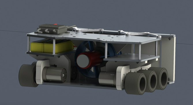
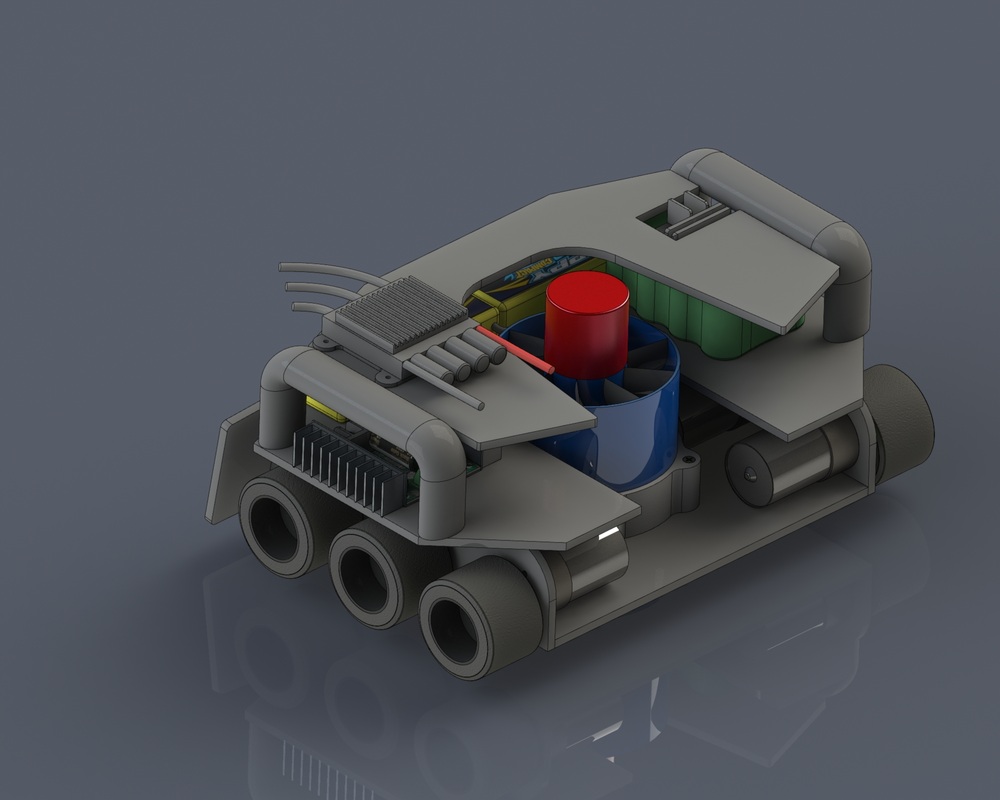
Lets get technical. There are six 12VDC gear motors with 152rpm and 16.7kg.cm of stall torque each. They have a 6mm output shaft and weighs about 7.28oz. All six motors will be controlled with a Sabertooth Dual channel 2x25A systems. As far as my secret weapon goes, 90mm EDF unit with 3400 watts can produce a maximum thrust of 10.8lbf at 10s LiPo. Since the EDF is going to pull a lot of juice, it is hooked up to a Turnigy Superbrain 100A ESC. They comes with data-logging capability, which is a nice feature that is going to be handy during the testing phase of the robot. At this point, I am planning to integrate two independent batteries for the drive train and thruster. Sealed Lead Acid batteries for the drive platform and Lithium Polymer batteries for the thruster. SLAs should provide the required extra weight and sufficient amp draw rate.
I am satisfied with the design and specification aspects, so lets get to the fabrication. Considering the amount of mumbo-jumbo theories and expectations floating around the thruster idea, this sumobot gonna need a lot of testing and data collection before I put it up for a fight. Above all, its not just to fight for money, its about learning the fundamentals of research and development aspects of engineering.
I am satisfied with the design and specification aspects, so lets get to the fabrication. Considering the amount of mumbo-jumbo theories and expectations floating around the thruster idea, this sumobot gonna need a lot of testing and data collection before I put it up for a fight. Above all, its not just to fight for money, its about learning the fundamentals of research and development aspects of engineering.
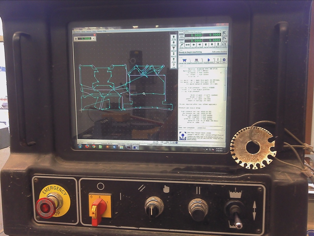
I pulled out all the pieces that need to be cut out of aluminum and HDPE and made DXF files of them for the CNC waterjet cutter. I would prefer a laser cutter any day to cut my pieces, but, unfortunately, the laser cutters at Louisiana Tech University wont cut metal pieces or HDPE. HDPE would have been possible if it were to not melt badly, but unfortunately it does...BADLY!
The most exciting part of any build project is the moment when your CAD files turn into a part in real world. That moment of birth at the Protolab where u touch and feel the part is just beyond words. Anyways, parts are cut.
Not sure if I ever mentioned it before in any other build thread that HDPE is nastier to cut using waterjet. Since HDPE is buoyant in water, when you cut it using waterjet, it creates residues that floats. So, it pretty much make the machine looks like it has Rabies. Metal cutting is not messy since most metals are denser and the residues sink down. Anyways, some extra clean up after cutting and the lab monitor will hate you, that's all.
The motor mount part that was cut out of HDPE needed some machining to drill a 1.5" diameter hole 0.3125 inch deep. The 12VDC gear motor face has a diameter of around 1.44in or so, so I needed a 1.5in diameter fostner bit. So I hit the road to Lowe's as always. Here is the funny part, I found a Fostner bit kit by Porter-Cable but its only upto 1.375in diameter. I needed the 1.5, which apparently is the next big size after 1.375 bit series and its not included in the kit. What is even funnier(or unfortunate) is that the kit cost around $19, which I was drooling to buy, and the ONE drill bit that I needed cost around $19 each!!! Hey business people, why-you-no-make-sense?
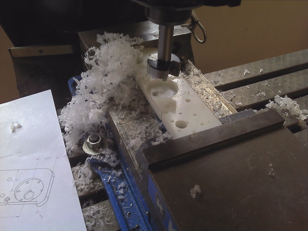 | 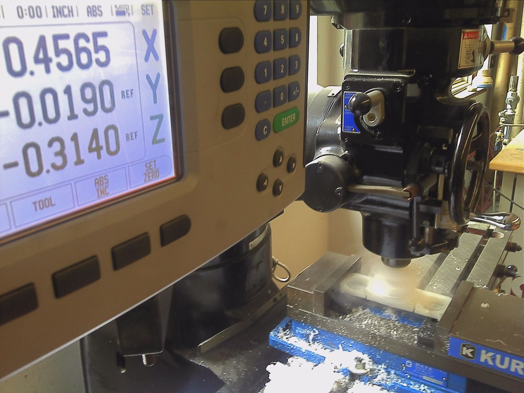 |
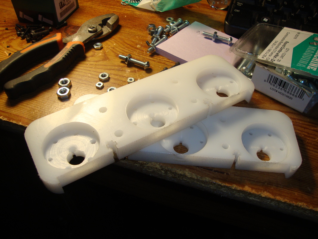
Machining went well except that I made some mistakes in not calibrating the Z axis properly so its off one or two thouandths off which is no big deal. I also had the part tilted slightly which would cause the motor to orient slightly in an angle when face mounted. Minor issues but, surely, a good learning lesson. There they are after some cleaning up at home.
I spent too much time on research, brainstorming and design aspects of this project that fabrication is the quickest part. In fact, the goal is to assemble the parts in few hours and I should be driving this thing by the end of the day, at least thats the plan. we will see. Ahhh...its time to get a can of Dr.Pepper from the fridge and pour all the screws and bolts into my desk for a good build.
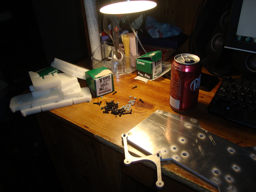

Most of my screws are Torx headcap 4-40 with square nuts. I had some left overs from the Bigfoot project. I did ran out of square nuts but made a quick trip to Lowes again to get some more. Lowes doesn't carry 4-40 square nuts so I ended up getting regular nuts which are hexagon shaped. They sure arent going to make enough surface contact inside the slotted cut on the parts I made for square nuts but it should work nevertheless. Good that it did work and the bolt dug into the HDPE part while tightening and made it lock in place so the joint holding force is plenty for the kind of forces Typhoon is dealing with. There are couple of places I have 10-24 screws needed, which luckly I also happned to have some left over from the previous projects. Just had to get some extra 10-24 bolts. Now, One component I wasnt sure if I could find in store was 1.5in standoffs and sure enough I did not find them in store. I dont want to order them online and wait for few days to complete the build as I am growing impatient to drive this puppy! ahem..ahem...this beast!! I ended up getting 2in long 1/4-20 bronze screws. Loved those golden bronze colors as well.
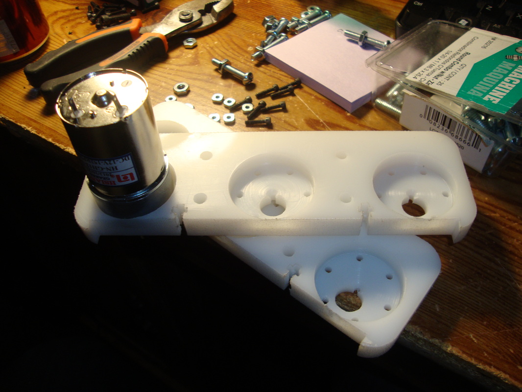 | 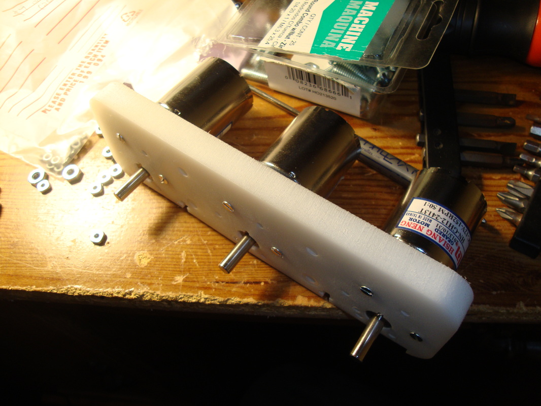 |
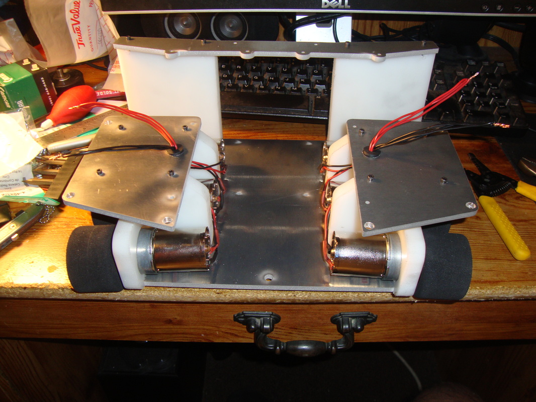
All motors checked and works. I added the base plate and the HDPE motor facemount part and it made a snuggle fit. perfecto! Notice the second can of Dr.Pepper ha!
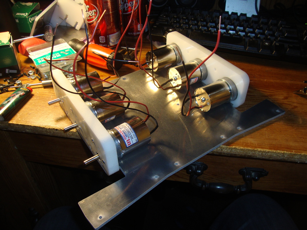
Wired and soldered in all the motors and added some colored heat shrinks to match the wire color. This is a habit i recently started after buying an assortment of colored heat shrinks from a Chinese eBay vendor. Gotta keep the wiring clean and secure since there will be a strong flow of air through the business end of the EDF. Definitely don't want connection wires shooting out through its butt. I honestly have this fear of components flying out after seeing the amount of air mass flow rate of the thruster while testing.
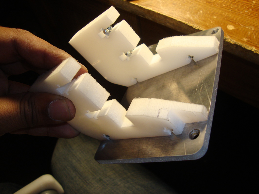
Oh, another part I had to machine earlier was the Midplate mount parts. There were four of them in total, but two of them needed a slight machining. There was this 1/4-20 screw bolts I mentioned earlier had to be secured in those mid plates. This was not a planned hole since the idea was to use 4-40 thread 1.5in long standoffs. Now, the 1/4-20 bolt instead chosen were interfering with the plastic piece so it had to be cut out using an end mill bit. There, this is the reason why I always prefer to pre-plan everything in CAD before start fabricating stuff. CADing make your life so much easier as an engineer.
So the Mid plate is mount and secured. It feels very rigid at this point. The purpose of the mid plate was to give some extra space to mount electronics and batteries. This was a lesson I learnt from Blackwidow project as I got carried away with asthetics too much and the determination of keeping it compact and dense. Well, I had issues back then not having enough space to secure all the components properly, but in the end I did managed to secure everything and it was super dense and difficult to access in case of emergency. Then I short circuited battery leads and shits were flying everywhere. Anyways, more space...more space is good!!
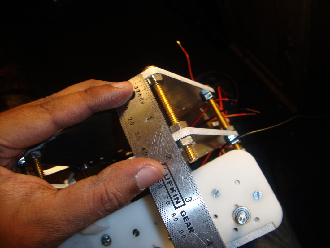
Since I am not using 1.5 inch standoffs, here is some ninja measuring skills for your viewing pleasures. I think I liked the idea of using screws rather than standoffs. Oh I also liked how neat that waterjet cutted the aluminum. Look at those pretty smooth edges.
I bought this rubber gromits from Lowes. I do not reacall the exact size but it doesnt matter as I had to cut it to make it go through the holes anyways. I had to cut out holes on each side of the robot for routing the wires. The hole for the wire was intentionally left out from the CAD drawing for the CNC cutter as I needed to feel the flow of wire to make that decision. The solid core 20AWG wires are all tucked away and routed through the hole and left it there. I haven't made a decision on where the battery and motor driver is going to be located yet. I do have enough room to make a decision on that later on however, so I moved on to the next on assembly check list.
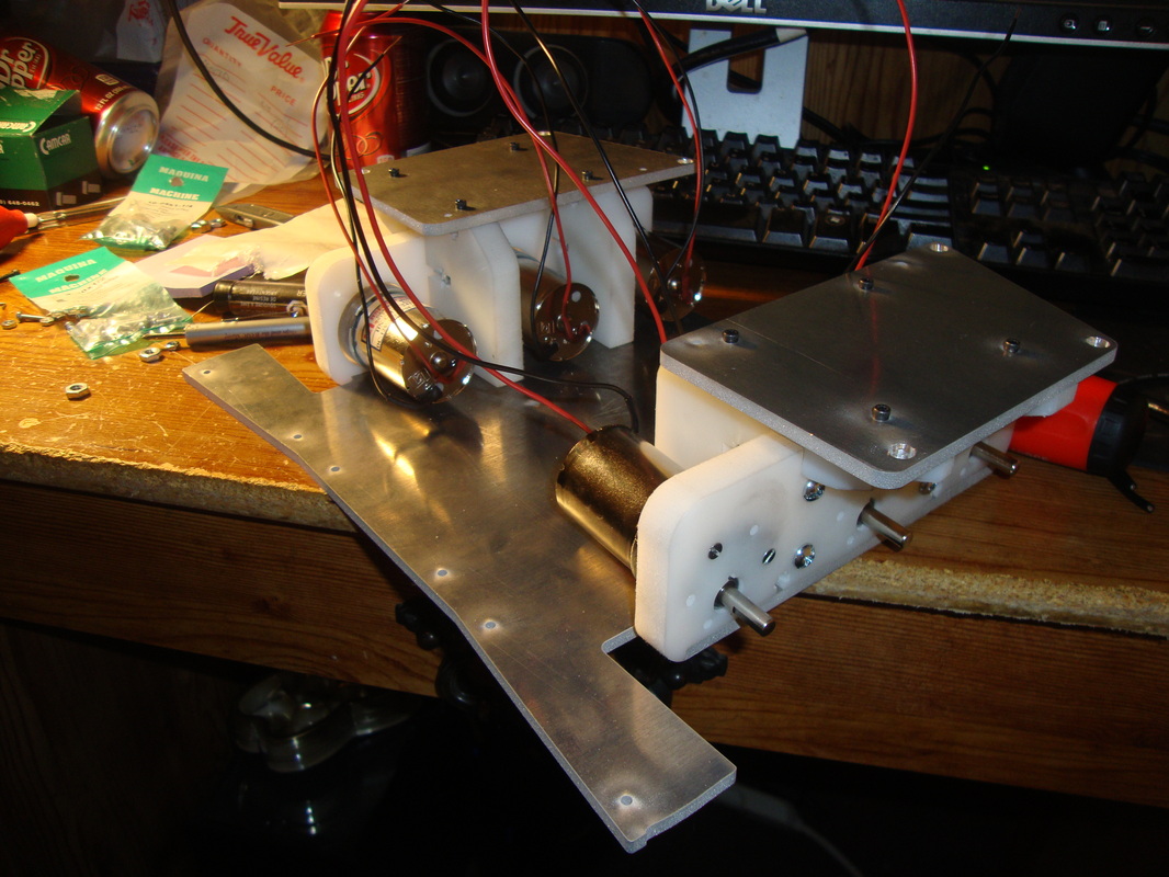
So there it is, the first glimpse of Typhoon in its early stages. I have my trusty Casio out for size comparison. Its quite big and boxy in a good way, at least to my taste. I am loving every bit of this project. The front Blade has a curve built into it so that when it comes in contact with an object, it auto-center it for better pushing orientation. I left the middle plate out for now till I fully install the EDF unit as it can only be placed inside through the front. I am not going to paint this baby, just love the natural finish of aluminum and white HDPE with golden and black colored screws. Okay, enough making dorky statements about its aesthetics, the ultimate goal is to make it mean, not necessary beautiful.

Most of the mechanical components are mount and the only hardware left to secure is the EDF itself. I need to cut out or 3D print the brackets sometime soon. But till then, I could hook up the motors and do some testing. I wish if I had a xbee and current/voltage sensors to assist in data collection and motor performance etc. I need to add those into my 'bucket list' or find a better mall Santa to sit on. With motors and chassis, it weighs 8lbs which is roughly half the target weight. I am in good shape and have plenty of room for heavy components. Heck, I might even consider a small sealed lead acid battery to power it. That would take care of the extra weight part and battery part in one shot but it might require a rectangular cut on the top plate as I would really hate to put it on top of the top plate. One thing will be sure, I cannot make it top heavy as I prefer the center of gravity closer to the ground.
Well, that escalated pretty fast. Just stuck in the EDF without brackets to get an idea of what it would look like. I have a feeling that there is going to be a lot of wiring stuff involved ahhh. Mounting them all rock solid is going to be the big deal.
So the ground clearance of the robot after fabrication is 0.3875 which is about 0.0001 inch off from the CAD. I say thats pretty good! During testing, I was asking my brothers what could possibly go wrong during the competition and he suggested what if the opponent has a wedge shape blade? well he is right, the 0.3875 in ground clearance is a big deal. During testing, the robot just drove over through the wedge instead of blocking and pushing it off. I might add a flipper blade fin to the flat blade in a way that it can be actuated using a servo. The flipper fin will have a wedge shape that that would ensure the opponent has no choice but to suffer the wrath of typhoon. Its an optional thought that I would consider if I have enough time and funding. At this point, the robot is good to go.
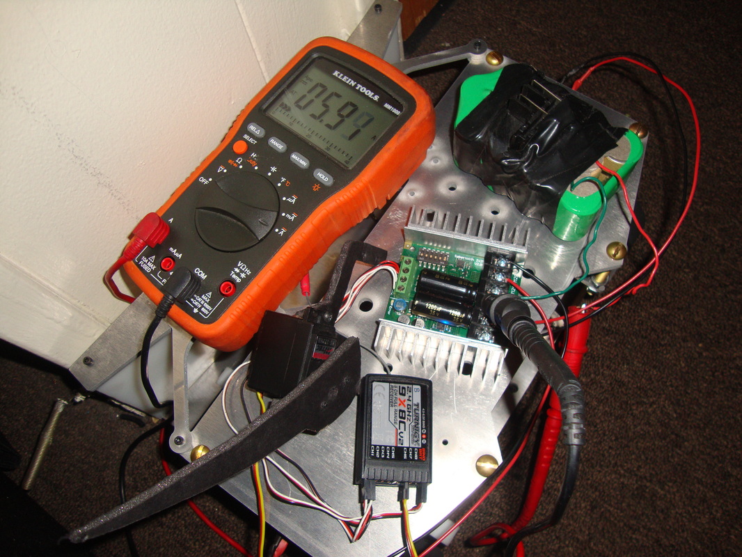
Till I get hold of a voltage and current sensor to plot the performance, multimeter is the way to go. I placed the robot against a wall and hit the throttle to max and read the amp loading pattern. It read a 400mA when the robot was idling and I was first confused, but then realized that I had all the electronics including the radio receiver still hooked up and running. Sabertooth outputs the 5V to power the radio receiver so its constantly using up current even when its not powering the motors. The multimeter is connected at the battery instead of the motor. So it makes sense to read the 400mA even while idling. Then I pumped the throttle up and noticed the multimeter displaying over the limit error message then displays around 6 amps. So I went back to the user manual of my Klein Tool MM1000 mulitmeter and realized that its ammeter range is only upto 10 amps. So, initially Typhoon's drive train is definitely pulling more than 10 amps then drops down to 6 amps. Thats how motors work anyways; they pull a lot of juice to get started then drops down. A sad lesson learnt from the Great Frying Of Adafruit Motor Driver Shield during my early years. Since sabertooth 2x25A are rated at 25 amps per channel, I am good to go this time. I will be making a detailed observation on the power and performance aspects later on, hopefully. As for now, everything is working well, as it should be.
So, the hardware is mostly built and assembled and the last few parts to integrate were the EDF itself and, ofcourse, an appropriate battery and the wiring. To be honest, as far as the post assembly is concerned, these took me a while to figure out on how to go about it.
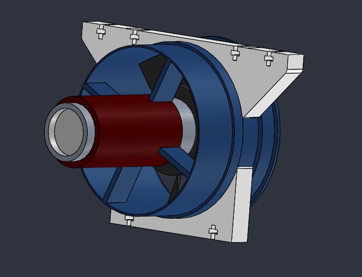
Even though the 90mm EDF came with a default, mounting straps, there were not useful for my hardware. Therefore, the EDF is mounted using custom made brackets. I decided to use the left over 0.5" HDPE to waterjet out the parts and mount it in a sandwich manner as shown in the figure. The EDF has a 0.51" groove for the default bracket to wrap around its metallic shell.
So, the hardware is mostly built and assembled and the last few parts to integrate were the EDF itself and, ofcourse, an appropriate battery and the wiring. To be honest, as far as the post assembly is concerned, these took me a while to figure out on how to go about it.
Even though the 90mm EDF came with a default, mounting straps, there were not useful for my hardware. Therefore, the EDF is mounted using custom made brackets. I decided to use the left over 0.5" HDPE to waterjet out the parts and mount it in a sandwich manner as shown in the figure. The EDF has a 0.51" groove for the default bracket to wrap around its metallic shell.
The first issue was that I do not know if the groove on the EDF will be enough to support around 11 lbs of thrust using a ductile plastic bracket; the second issue was that there was no left over plastic piece left. First issue is purely and engineering problem that can be solved.
Figured I would go ahead and 3D print the brackets. I have this 1Kg roll of 1.75mm PLA filaments that I brought from Matterhackers laying around, so why not use them. PLA does have reasonable strength in appropriate build volumes. For my purpose, a 35% build volume seemed to work. Since the groove is 0.51", I can print it upto 0.51 for a sung fit instead of worrying about being mounted 0.01" loose from the 0.5" plastic piece I would otherwise have used. So, there I am ready to hit the Thingery makerspace to use their Makerbots once again.
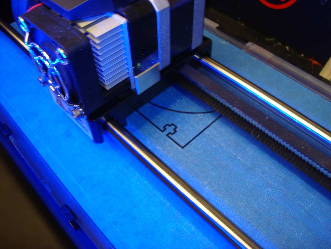
I wanted to make sure the CAD model of my EDF has accurate dimensions compared to the real one. If the diameter is not good enough, then the bracket wont be a snug fit. So, figured I should make a test print before doing the full thickness extrusion. Learnt from the Bigfoot project that to confirm CAD dimensions before rushing to cut or use the build materials. The bracket diameter seems to be a good fit so I went ahead and printed the parts.
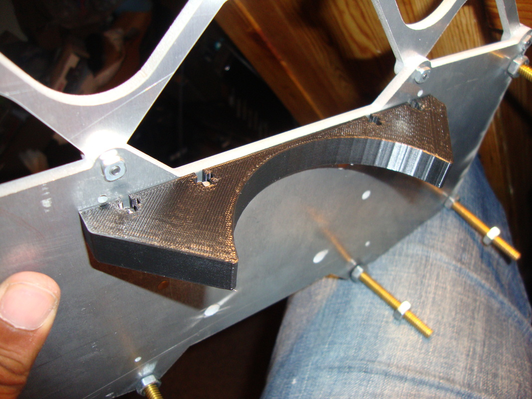
The EDF is finally mounted securely. The bracket seems to be a good fit and there is no wiggle room for the EDF. Applied some Locktite on all major screw threads to make sure they wont come off while in operation.
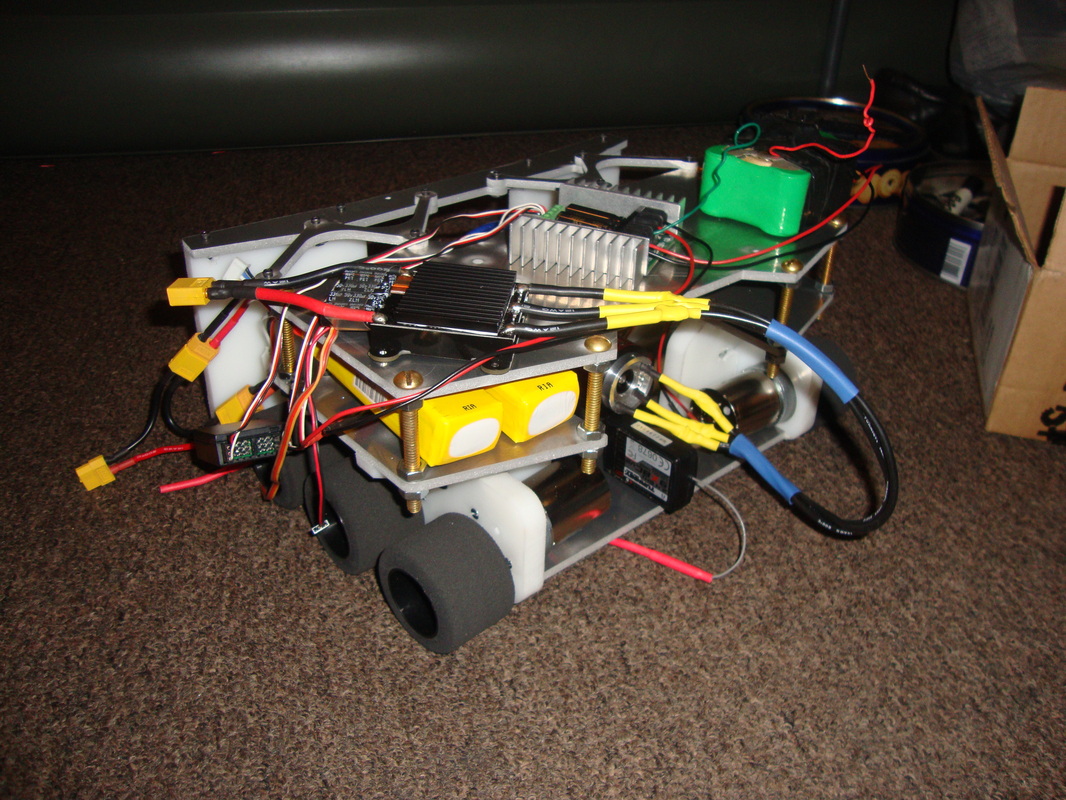
Check out this image below with EDF mounted. Notice that I replaced the yellow 4s LiPo batteries with the blue 5S LiPos for the EDF. The previous ones were two 1.5ah and 25C only which is not a good configuration for the ~100A EDF. So I made the call to replace them with 40C, 5S, 4ah LiPo. EDF is rated for 10s so the batteries are arranged in series to supply 10S.
Check out this image below with EDF mounted. Notice that I replaced the yellow 4s LiPo batteries with the blue 5S LiPos for the EDF. The previous ones were two 1.5ah and 25C only which is not a good configuration for the ~100A EDF. So I made the call to replace them with 40C, 5S, 4ah LiPo. EDF is rated for 10s so the batteries are arranged in series to supply 10S.
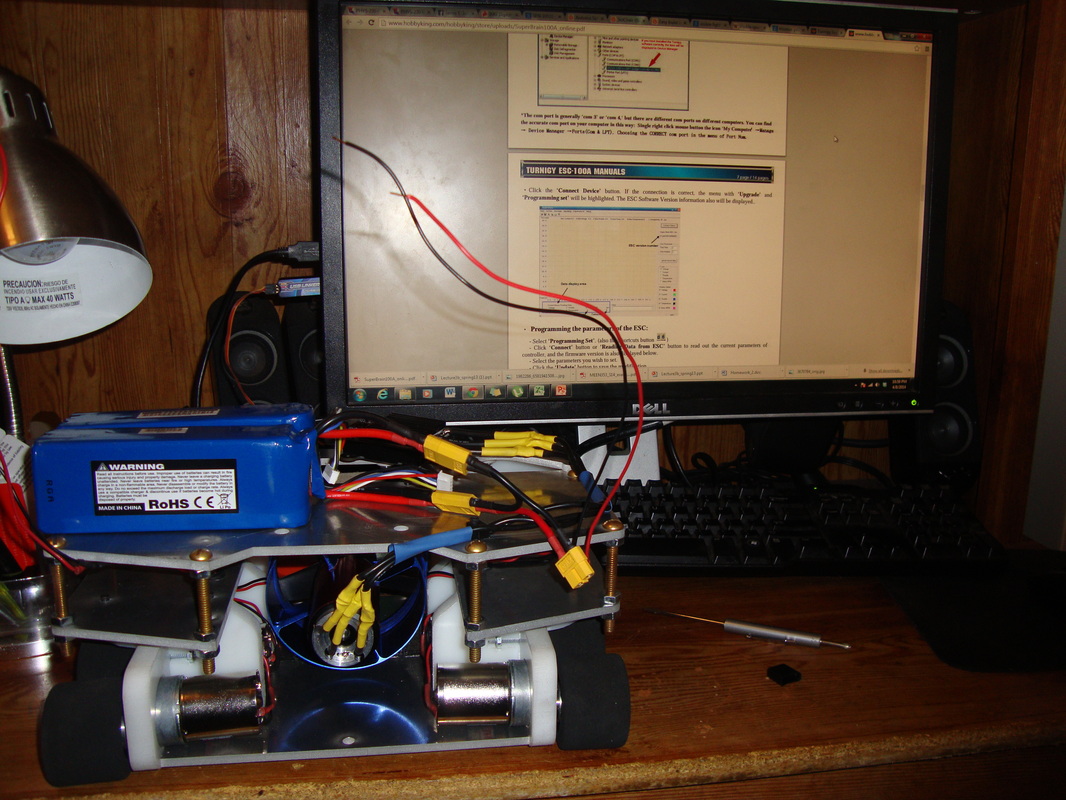
Well, something terrible happened right after taking this picture. Once the EDF is secured, I wanted to program the Turnigy 100A superbrain ESC before I can turn it on. I bought the USB datalogger to access the extra features of Superbrain ESC using PC and it can be programmed directly from PC using the datalogger. Since Superbrain doesnt have a built-in BEC, you need to power it to access the it using the computer. There are two ways you can power this particular model. There is an extra 2 wire power line (similar to the 3 line signal wire) you can use or you can connect batteries to the main line. Since I didnt bought the accessory wire that needed to turn on ESC using signal wire power line, I chose to power it up using the main line with 10S. The 3 line ESC control wire goes to the Datalogger pins on the back side. The other end of the datalogger is a USB plug that connects to the PC port. So I downloaded and ran the software. So far so good. Then I hit the connect button and BAM! my monitor gave me a blue screen and system crashed. I got restarted to a "Grub Rescue" window.
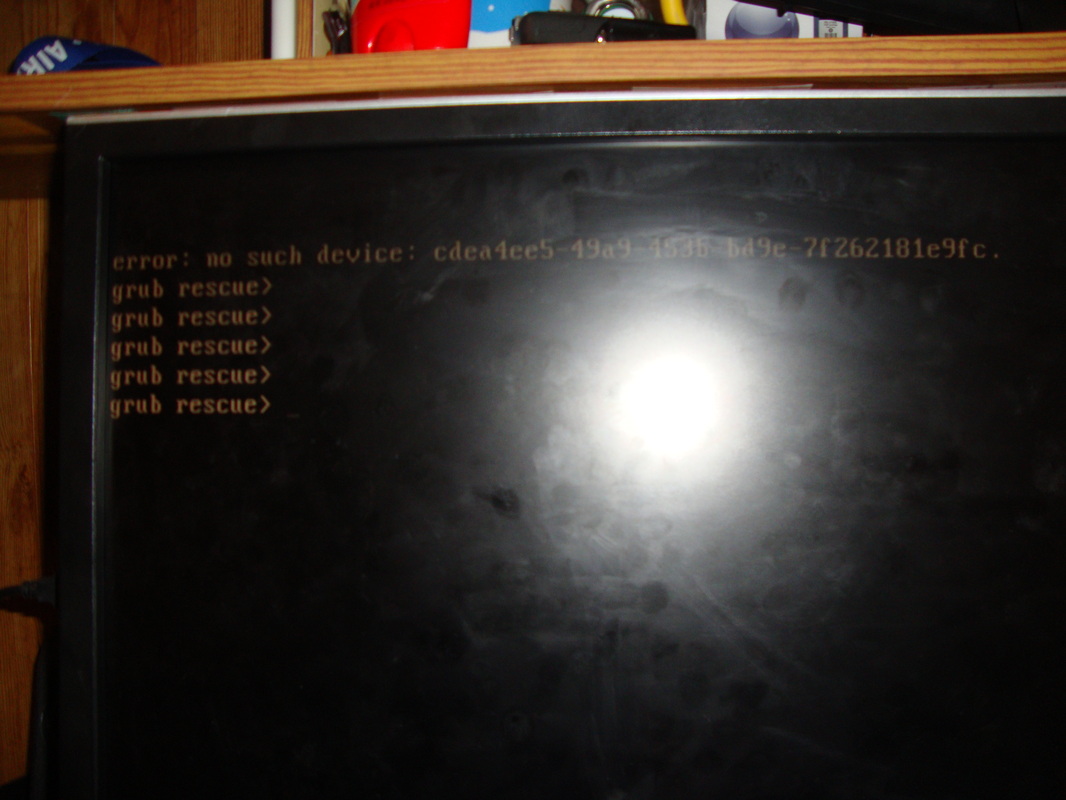
Not sure what exactly happened but I am assuming there was a power surge on the USB port from the ESC which caused issues or it could be the that turnigy program caused issues. Not sure what exactly happend, so I googled and figured out a way to get out of this mess. My only wish at this point was that I didnt fry my motherboard or any other PC components. It worked out fine after running Windows installation disc and repair feature etc and after some frantic few hours, system is back up running. I still had to program the ESC, so I hooked up one 4S LiPo instead of two 5S LiPos and again, it went to blue screen again but this time It booted back to windows instead of grub rescue window. Anyways, I tried the same on my laptop and it connected without issues and I programmed the EDF finally. Now we are back in business!
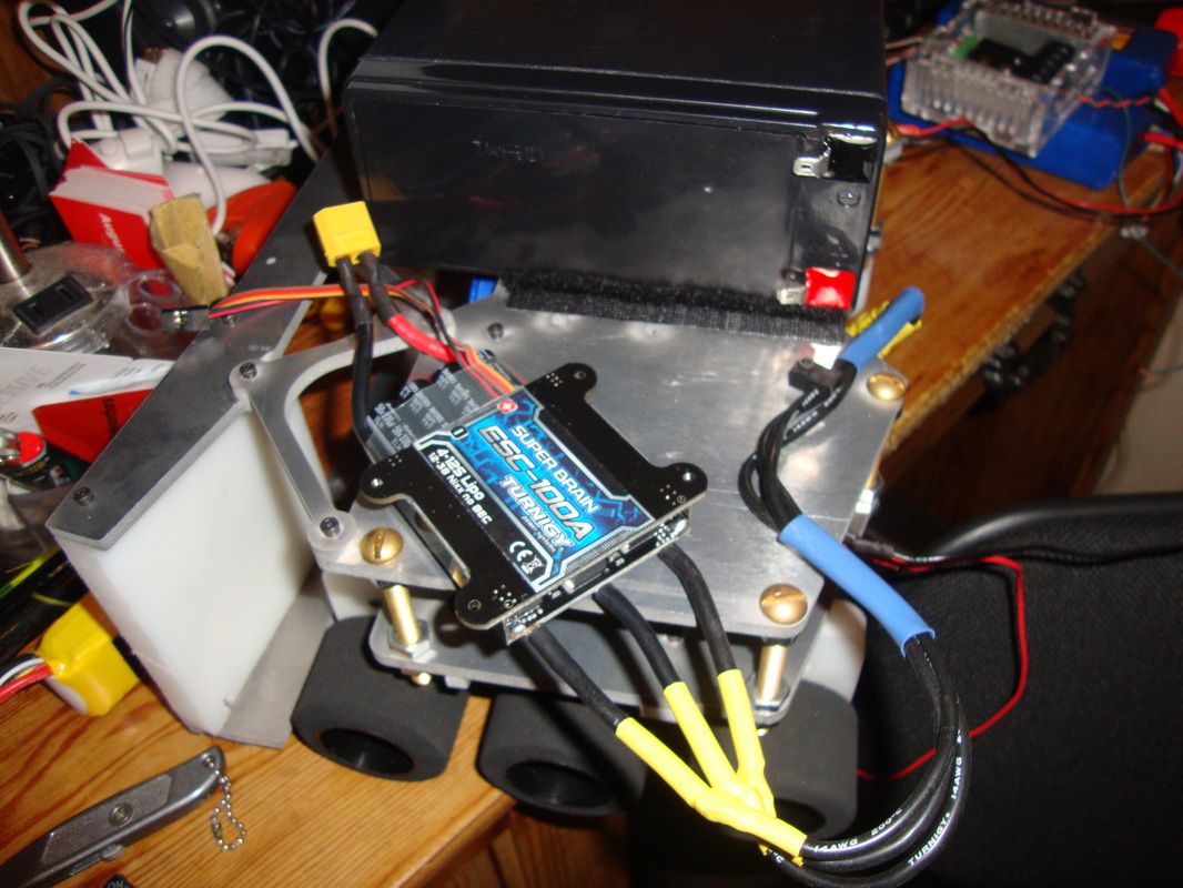
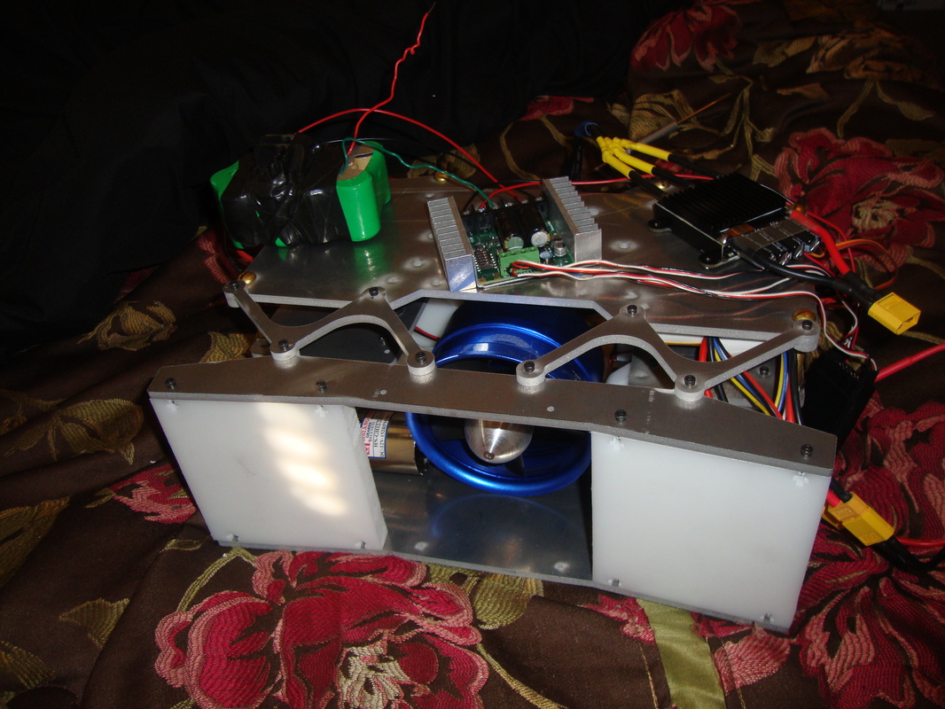
I finally made my decision on the batteries. I needed some cheap, realiable and high amp output battey. The primary choice were the LiPo or Cordless drill batteries or Sealed Lead Acid batteries. In the mean time, IEEE upgraded its weight class from 15lb to 20lb. Now I need to worry about getting some dead weight since the robot without batteirs weigh a little over 10lbs. Now the silver bullet to get two birds in one shot is to buy a Sealed Lead Acid battery as they are cheaper, heavier and have a good amp-hour rating. Only issue is the volume since I dont have space to tuck it inside, it has to go on the roof. You can see the SLA is mounted sideways using industrial strength velcro from Lowes. Am sure the SLA is supposed to be mounted upright but that would raise the center of gravity. As far as storage of the robot goes, the whole robot is kept flipped sideways up to make sure the battery is placed upright. I am using Velcro to mount the ESC, SLA battery, EDF's LiPo batteris, Sabertooth enclosure etc. It seems to be holding up pretty well.
Another interesting find is that the foam wheels are so sensitive to weight that if you kept the wheels touching the ground for a while, the point of contact on the wheel start to flatten. They will expand back to normal after a while if you take the load off however. In order to avoid this issue, both Blackwidow and Typhoon are stored on a jack that keep the wheels lifted off the ground.
So how robust is the assembly so far? Here it is all 18lbs!
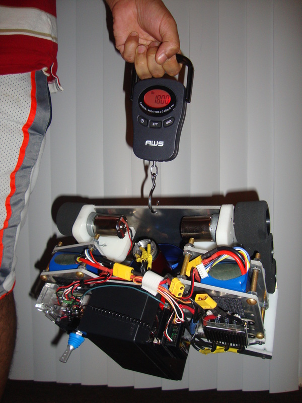
Its 18lbs, I will be adding that extra 2 lbs to make sure its 20lbs for the competition. nothing more nothing less.
It still was 2lbs short of the target 20lbs so I taped up a 2lb sheet of steel I took off from Blackwidow (since I had to get rid of some weight from her to make it eligible for the light weight, so it worked out). In the end it was finally ready for some actions.
It still was 2lbs short of the target 20lbs so I taped up a 2lb sheet of steel I took off from Blackwidow (since I had to get rid of some weight from her to make it eligible for the light weight, so it worked out). In the end it was finally ready for some actions.


Typhoon took the first place home! He was built for one purpose, and that purpose was accomplished in flying colors.
