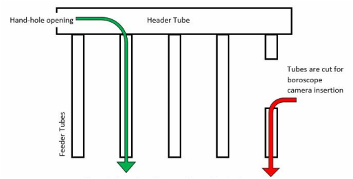
 Figure 1. Current method (red) vs proposed method (green)
 Project Scope and Problem Statement
American Electric Power (AEP) is sponsoring the Louisiana Tech University Capstone senior design team for the research and development of an automated boiler tube inspection device. The device will be used to inspect fatigue corrosion in the header and feeder tubes to improve the reliability and safety of their boiler systems. Augustine Aelavanthara, Avinash Maskey and Rabi Basnet will be designing the device as part of their Capstone Senior Design project. The group will be working closely with faculty adviser and industrial sponsor representatives from American Electric Power. American Electric Power is a major investor-owner of electric utilities in the United States. Based in Columbus, Ohio, the company provides electricity to more than 5 million customers across 11 states. Under AEP’s ownership, South-Western Electric Power Company (SWEPCO) supplies electricity to the Eastern Texas, Arkansas and Louisiana region. Being an integral part of its operation, the maintenance of its boilers is one of the critical parts of SWEPCO’s operations.
The primary concern SWEPCO has on the maintenance aspects of their boiler system is the corrosion fatigue to the feeder tubes. The asymmetric expansion and contraction of the boiler tubes, due to the hot steam flow, develops corrosion fatigue cracks inside the feeder tubes over time. If left neglected, such cracks can develop further and lead to disastrous results for the company and its operations. Currently, a section of the feeder tube is removed in order to create an insertion point for the boroscope camera. Considering the scale and total number of feeder tubes that requires attention, such inspection methods can be expensive and time consuming. Therefore, an alternative inspection method is proposed that utilizes the “hand-hole” as an entry point for the inspection camera.
Figure 1 illustrates the header and feeder tube orientation on a typical boiler system.
On Figure 1, the red arrow represents the current inspection methodology which requires the removal of a section of the feeder tube to create an entry point for the boroscopic camera. The green arrow represents the proposed, alternative inspection procedure that eliminates the need to cut feeder tubes. The proposed new inspection method will allow significant cost saving for SWEPCO as it is much less time consuming and more efficient.
Field Observation
Our site visit to AEP plants at Shreveport, Louisiana and Avinger, Texas proved to be crucial in our initial conceptual design of the project. Onsite observation has given us a clear understanding of the working conditions and the challenges our design will have to overcome. The feeder tubes were observed to be of various sizes and branching configurations from the header. Also, the locations of the hand-holes in the outer annular surface were different than our initial knowledge of being at the front face. We also noticed that some hand-holes were positioned in tight spaces.
During our visit, we have observed that the hand-hole can be located on the end-face as well as the side of the headers. Figure 2 shows a header tube with hand-hole located at the end-face of the header.
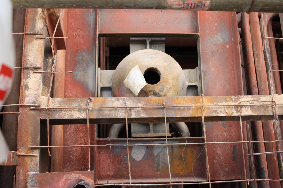
Figure 2. The hand-hole is located on the end face of the header.
We have also noticed that some headers have hand-holes located on the side of the headers. For instance, figure 3 shows a scenario where the hand-hole entry point is located on the side of the header.
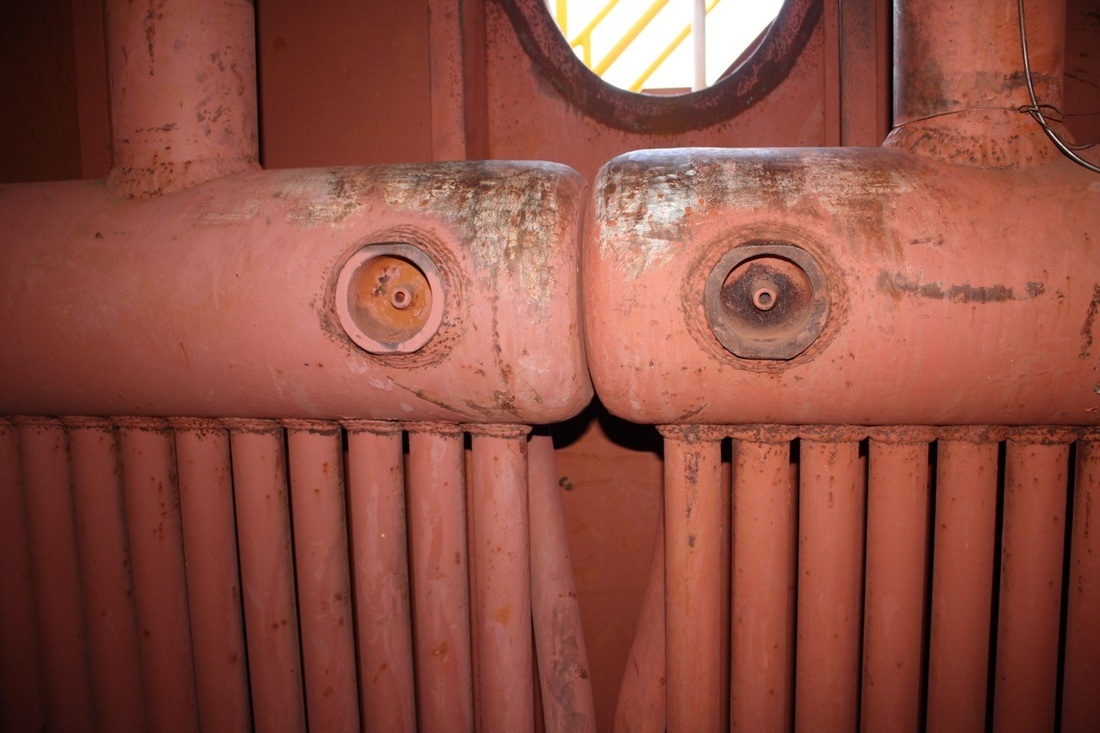
Figure 3. Headers with hand-holes located on the side
Since the side entrance requires a compact design no bigger than the internal diameter of the header, we will be considering all the dimensional aspects during the design phase. Another important observation was that not all header tubes were straight or oriented vertically from the base of the header. For instance, Figure 4 shows a header-feeder configuration in which the feeder tubes are branching from the sides of the header at an angle.
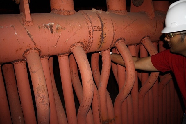
Figure 4. Feeder tubes branches from the side of the header
The documentation and analysis of branching feeder tube configurations, feeder tubes with s-bends, varying header-feeder pipe sizes and the piping networks will define the engineering specification for our design. We realized that our initial conceptual design of the video probe needed major modifications in maneuvering through these boiler tube configurations. The plant visit was fruitful in a sense that we were able to document and understand the challenges beforehand to better identify the design parameters.
Design Criteria In order to effectively tackle the project challenges, we need to define the design criteria. SWEPCO has identified specific requirements that will be the design basis.
Compactness: The device shall be compact enough to negotiate through tight spaces. Though the length of the device is open for consideration, the cross-sectional area of the device should be small enough to fit through boiler header dimensional constraints.
· Header Diameter: 6” to 10” OD
· Header Hand-hole Diameter: 3.375”
· Smallest Feeder Tube Diameter: 2.5” OD x 0.22” mw (minimum wall-thickness)
Position Identification: The device should be able to identify and display the geometric coordinates of the point of inspection.
Retrieval Mechanism: In case of failure, the operator should be able to retrieve the device and all parts in a safe manner.
Vision System: The device should have a vision system that can transmit and record videos for documentation and navigational purposes. It will be preferable for the user to have control over the camera’s orientation.
Ingress Protection: As one of the key requirements of the design process, the device should be rugged enough for use in an industrial setting. It is preferable to have ingress protection against solids and liquids for exposure limits that are common inside boiler header and tubes.
Reliability: The device should be reliable for extended use with limited maintenance. In case of parts failure, components should be easily retrievable and replaceable. No parts should come loose from the unit that would require search and retrieval.
Safety: The device should be safe during its operational life. For instance, there should not be any sharp edges or harmful wireless radiation associated with the device.
Our sponsors are open to new ideas and concepts to tackle the design challenge at hand. From our recent industrial visits, we were able to document and gather vital information that will substantially contribute to developing a meaningful solution. We believe by designing such an inspection device, we are not only pushing the boundaries of our learning experience, but we are tapping into the opportunity to significantly improve the efficiency of the industrial boiler tube inspection at an unprecedented scale.
Design Iterations
Concept 1: Rotating head
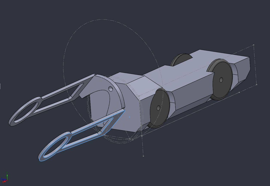
Concept 2: 2DOF manipulator
Concept 3: Flexible tail for isolated electronic enclosure
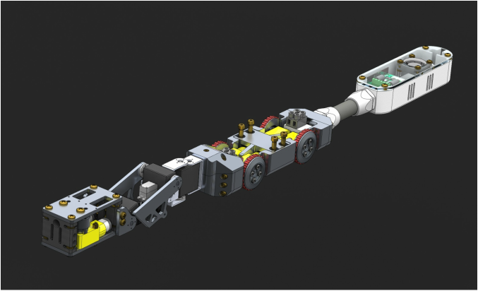
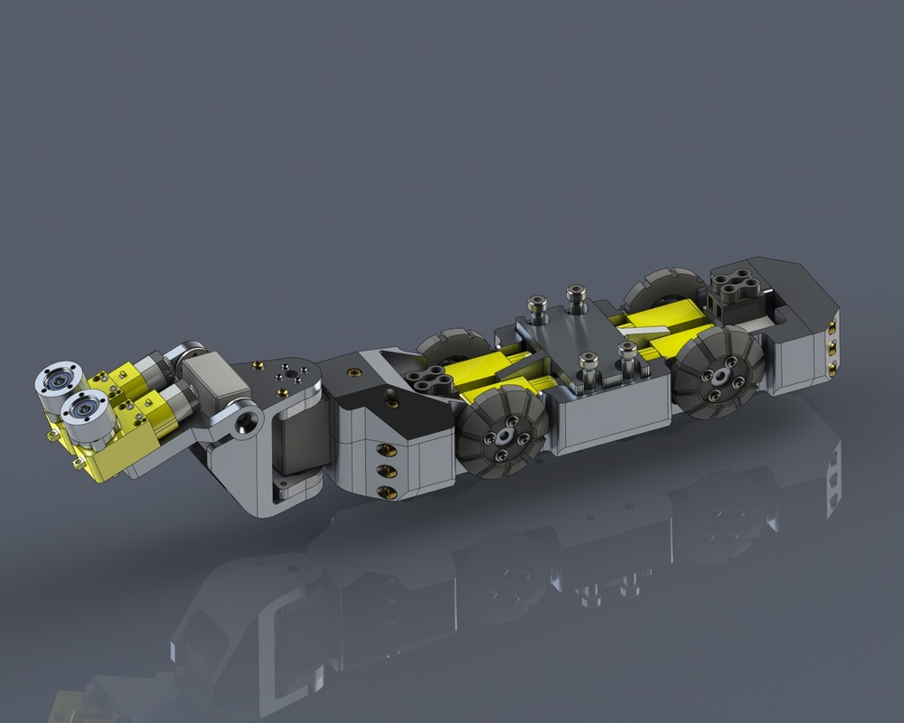
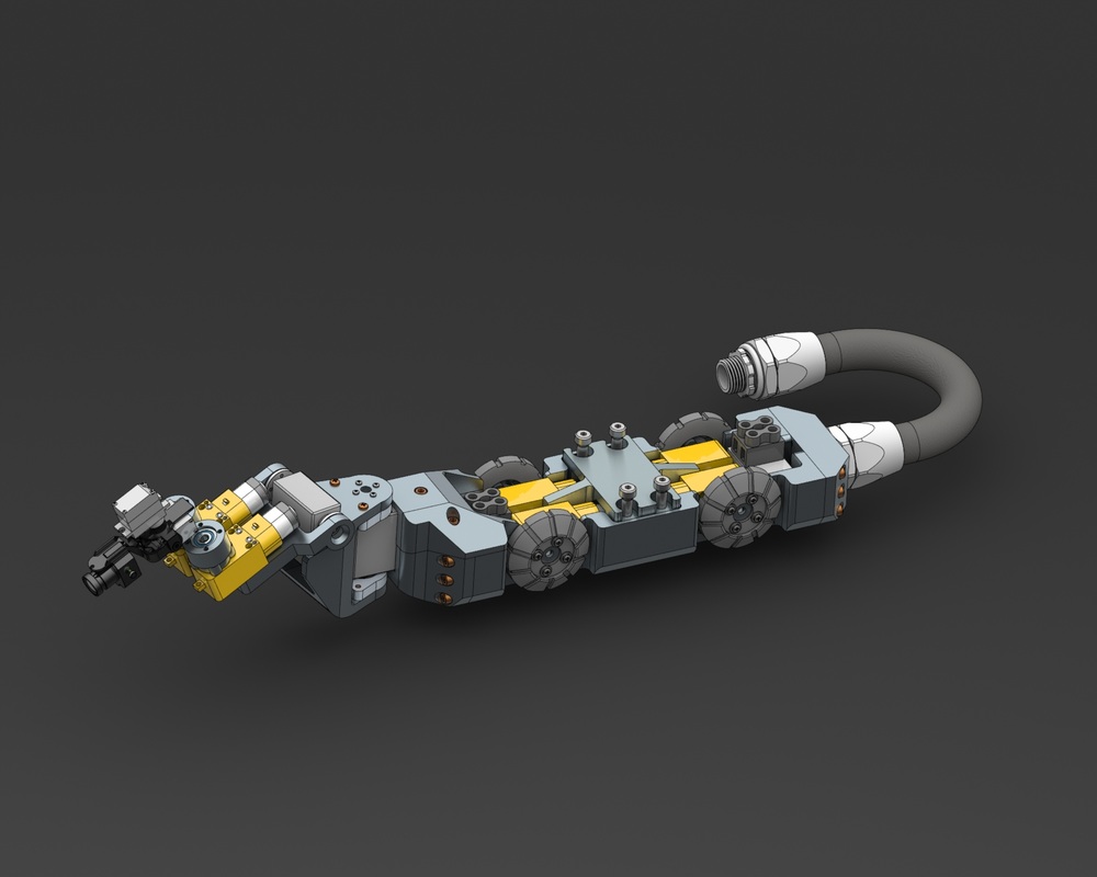
The design process never been stagnant. It was constantly evolving into a more refined solution as you can see from the various renderings shown above. Finally, I have narrowed in on the final version of the inspection device as shown below with an improved wheel treads, 3 DOF manipulator, refined feeder assembly, and an air-cooled electronics enclosure to isolate the components.
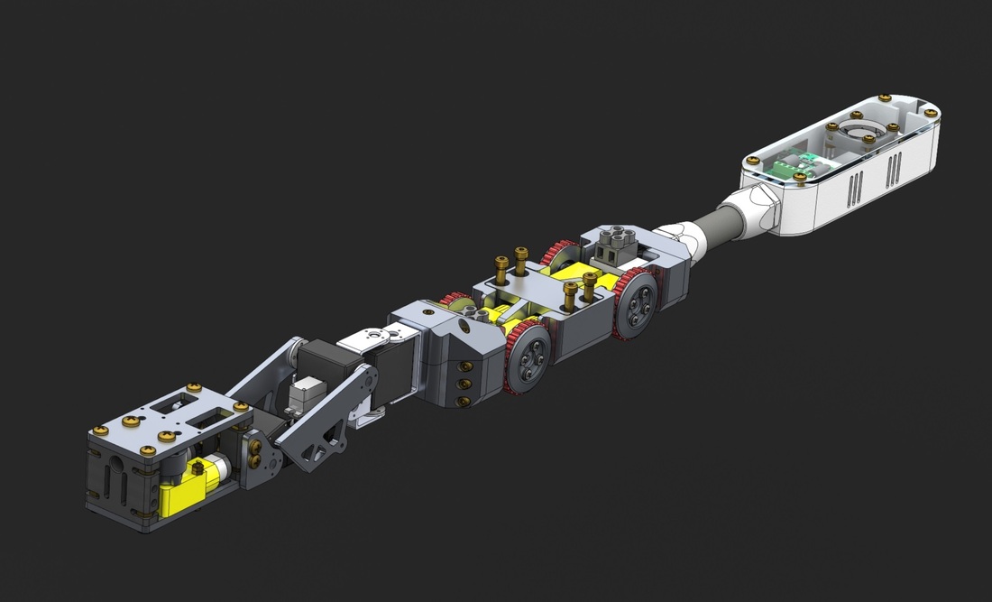
Concept 4: Improved wheels, feeder assembly, 3DOF manipulator, refined feeder assembly and an air-cooled electronics enclosure.
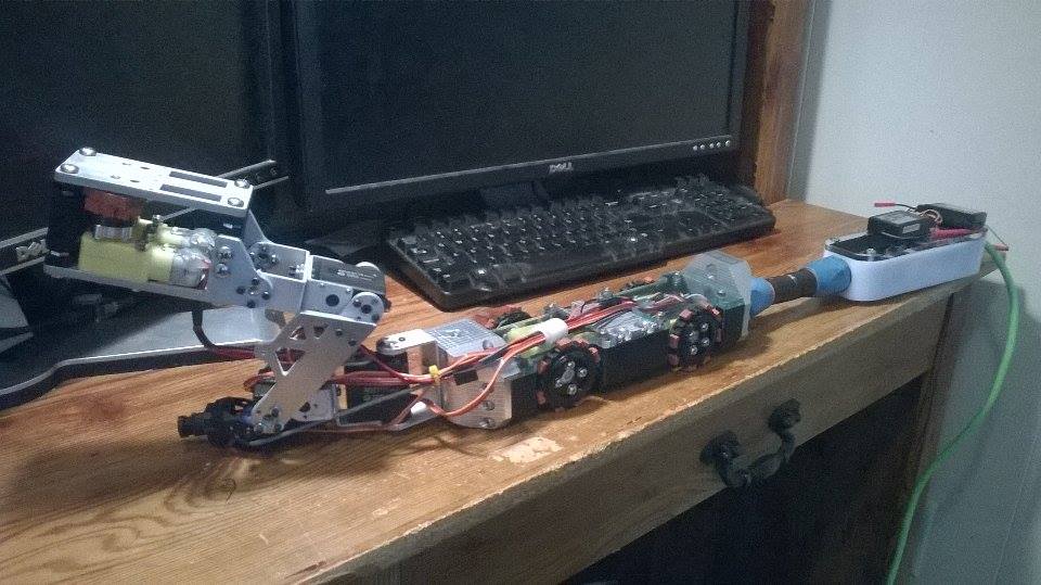
Fabrication
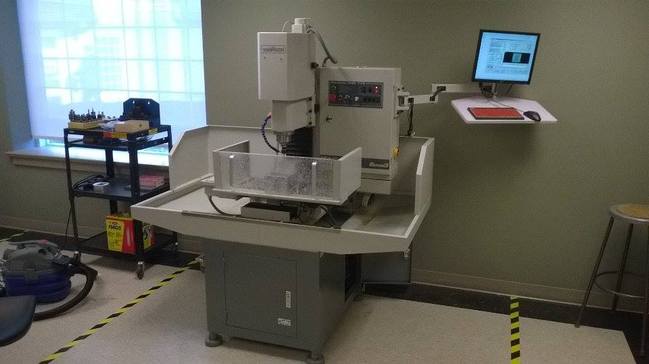 Tormach 770
 So, once the design phase is completed and most design issues were worked out, now I am onto fabricating the device.
Unlike all my projects before, I am going to use CNC milling machine for the first time to make parts. I am excited as CNC mills are capable of making metal/non-metal parts with complex shapes. 3D printers are great, but CNC mills will allow u to shape any material and you have full freedom to pick the desired material properties of your material. After all, a CNC milling machine is involved in the design phase of most consumer products.
The body will be machined out of 6061 Aluminum. I am planning to give some polished surface finish to make it look aesthetically pleasing as well. Louisiana Tech University recently bought couple of CNC milling and turning machines. Since the machines require G-code to make parts, I had to learn how to generate G-code. Its not easy for a beginner, but various tutorials and some in-person help with lab monitors helped me significantly. So, I use VisualMill add-in for solidworks to generate my G-codes.
So as far as I know, there are two CNC mills and one CNC turning machine for Louisiana Tech. I have heard there is another one somewhere in Institute of Micro-manufacturing facility. Anyways, all the fancy ones are right within my reach.
Haas TM-2P (Bogard Hall Machine shop)
Haas ST-20(Bogard Hall Machine shop)
Tormach 770 (Thingery)
I love Haas and Tormach. they are both great. For this project, I will be using the Tormach 770 mostly as its conveniently located in the Thingery lab.
I definitely did not want to cut my first part out of aluminum as they are kinda expensive. So, i went to lowes and bought a piece of 4x4 treated lumbers and cut them down to small chunks to use it as my experimental workpiece. Here is the result and it turned out great.
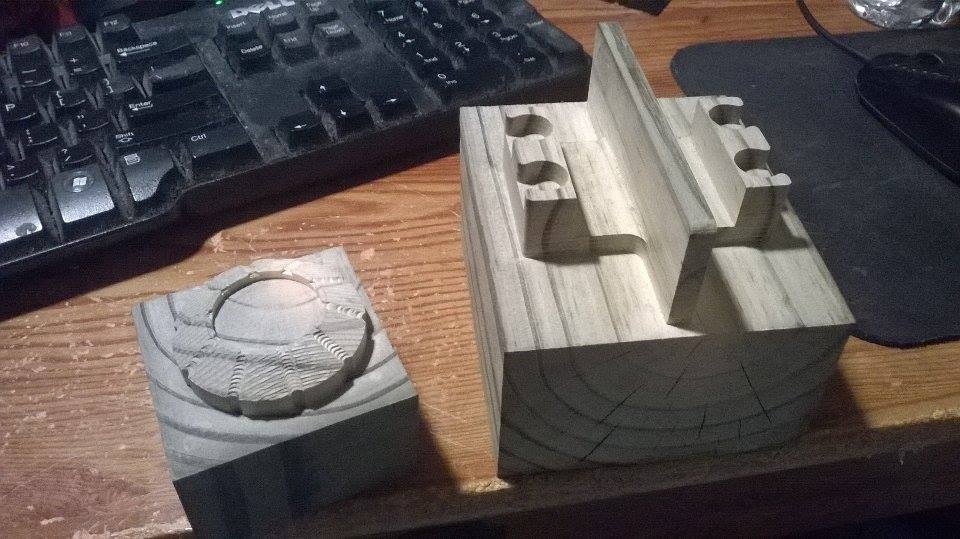
Working on wood pieces are great way to learn g-code and cnc-machines.
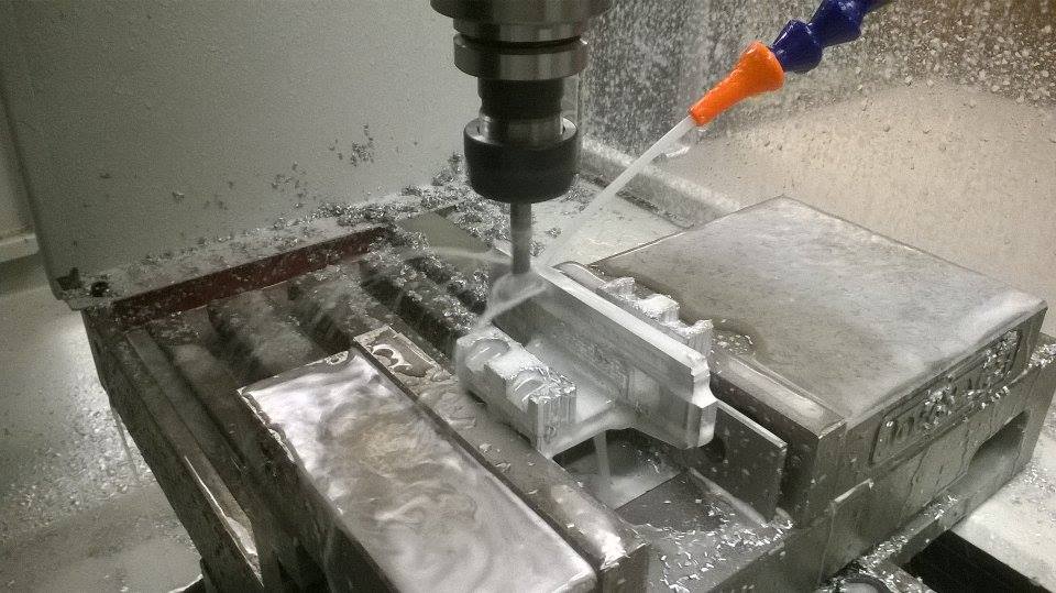
After figuring out how the G-code works, its time to make the switch to Aluminum piece. For the first try, I had to machine from the top, then flip the part to machine the other side. its going to be tricky to mach both sides.
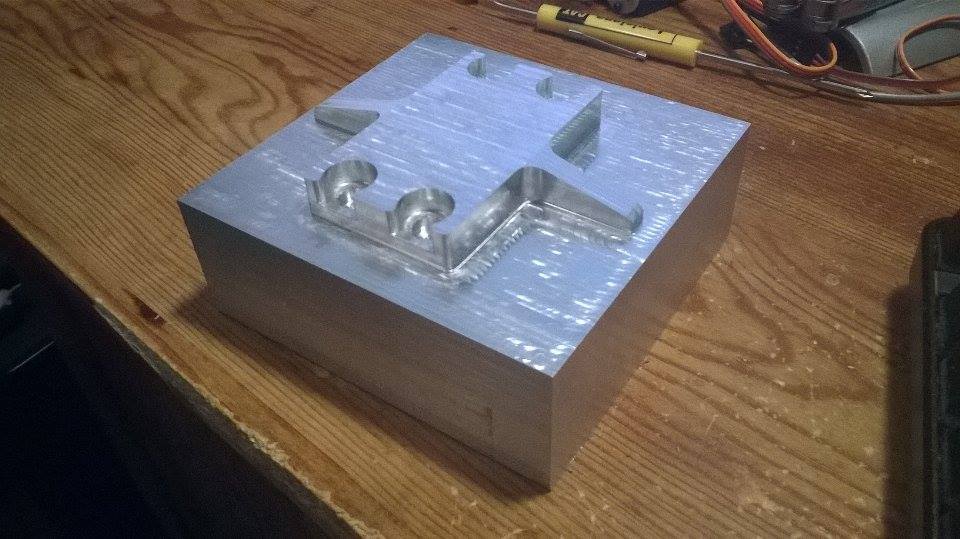
After machining the front side, I am ready to machine the back side.
Seems like both sides are matching up
So I flipped the part with some calculations. One thing i learned is that to make sure you machine the part dead center of the work-piece BUT make sure know the EXACT dimension of the work-piece also. I bought the work-piece knowing it was 4x4 but it turns out its little over 4, so the machining was not done at the perfect center. When you flip the part to do the other side, these minor offsets are critical. Anyways, I managed to add some extra calculations to compensate the error. Here is the final result.
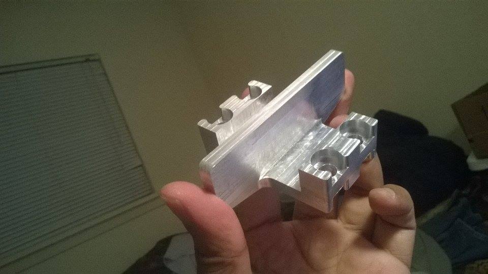
Final result.
Now that I am confident in using cnc-machines, I feel so empowered to create any kind of parts without having to worry about material properties -- a limitation of 3D printers. It feels like learning a new language or exploring new possibilities that were not accessible before. I am going to miss all these fancy machines when i graduate in few months. Anyways, now I have few more parts to machine using CNC mill.
 RSS Feed
